
Method for gas replacement of container and apparatus therefor

A container and inert gas technology, which is applied to packaging objects under special gas conditions, liquid bottling, packaging through pressurization/vaporization, etc., can solve the problem of reducing the replacement rate, the relative position has a limit, and the cap and bottle cannot be approached Nozzles and other problems can be achieved to improve the gas replacement rate, prevent air from reflowing, and prevent pollution

Active Publication Date: 2013-10-02
TOYO SEIKAN KAISHA LTD
View PDF1 Cites 0 Cited by
  • Summary
  • Abstract
  • Description
  • Claims
  • Application Information

AI Technical Summary

Problems solved by technology

However, in reality, since the bottle is close to the cap, there is a limit to the relative position where the cap nozzle can be close to the cap.
On the other hand, the same is true for bottle nozzles. Since the capping head is close to the bottle, there is a limit to the relative position where the bottle nozzle can approach the bottle.
In other words, there is an area where the "gas blowing nozzle" cannot approach the cap and the nozzle of the bottle
The air reflows into the inside of the cap and the head space of the neck portion replaced by the inert gas due to the area where the nozzle cannot be approached, thereby reducing the replacement rate of the inside of the cap and the head space of the neck portion by the inert gas

Method used


Image

  • Method for gas replacement of container and apparatus therefor
  • Method for gas replacement of container and apparatus therefor
  • Method for gas replacement of container and apparatus therefor

Examples


Embodiment Construction

[0041] Hereinafter, the present invention will be described in further detail based on the embodiments shown in the drawings.

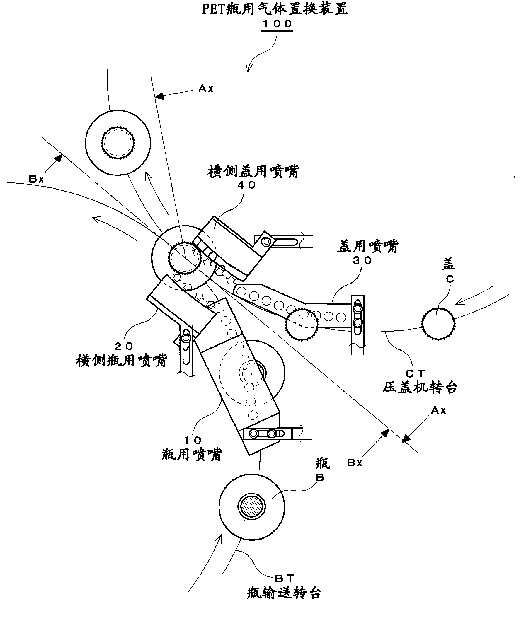
[0042] figure 1 It is an explanatory diagram showing the configuration of the gas replacement device 100 for PET bottles according to the present invention.

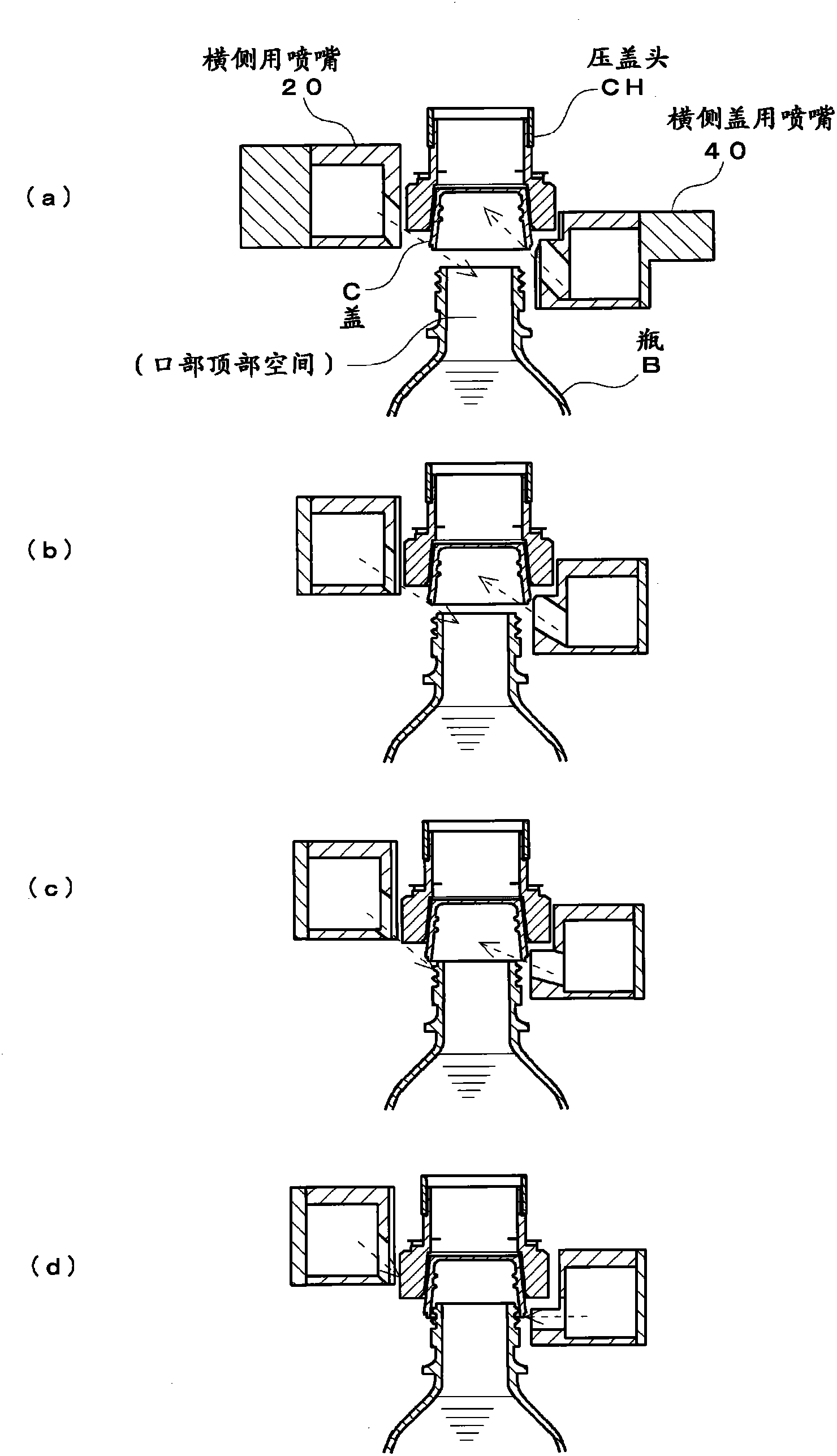
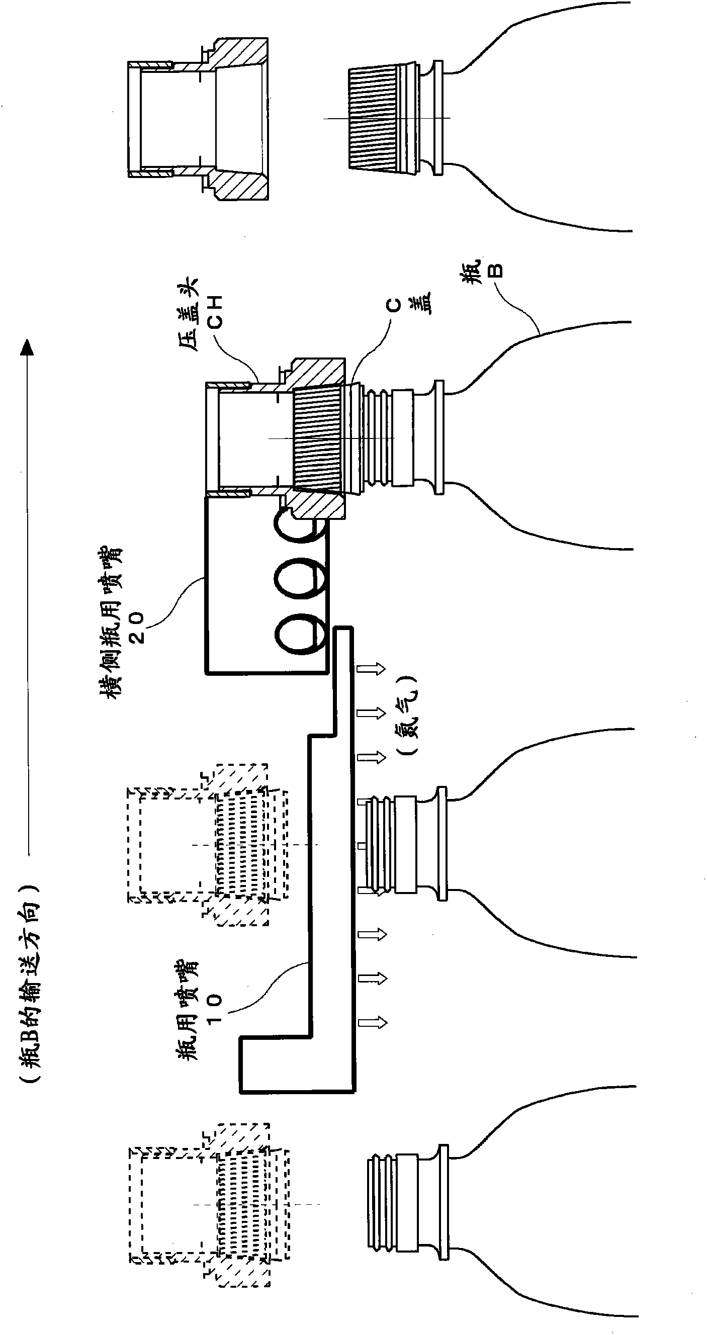
[0043] This PET bottle gas replacement device 100 is configured to include: a bottle nozzle 10 serving as a "first bottle nozzle" that flows nitrogen gas from above within a range that does not interfere with the capping head CH (not shown). The head space of the mouth of bottle B; the lateral bottle nozzle 20 as the "second bottle nozzle", after the gas replacement by the bottle nozzle 10 and immediately before the cap C and the mouth of the bottle B are fitted, the horizontal side The side bottle nozzle 20 allows nitrogen gas to flow into the head space of the mouth of bottle B from obliquely above; Inflow into the inside of the cap C; and the lateral side cap nozzle 40 as the "second cap no...


PUM


Abstract

Provided are a method for gas replacement of a container capable of obtaining a high replacement effect using a smaller amount of an inert gas, without spilling foam or content liquid at the time of gas replacement in a head space of the container, and an apparatus therefor.  A bottle nozzle (10), which is arranged in a range wherein it does not interfere with a capper head (CH) introduces nitrogen gas from above into a mouth of bottle (B) which has been conveyed, and a lateral-side bottle nozzle (20) arranged to avoid interference with the bottle (B) and the capper head (CH) introduces nitrogen gas from an obliquely upward direction into the mouth of the bottle (B) until just before the bottle (B) is fitted with the cap (C); while a cap nozzle (30), which is arranged in a range wherein it does not interfere with the bottle (B) introduces nitrogen gas from below into an inside of the cap (C) which has been conveyed, and a lateral-side cap nozzle (40) arranged to avoid interference with the bottle (B) and the capper head (CH) introduces nitrogen from an obliquely downward direction into the inside of the cap (C) until just before the cap (C) is fitted with the bottle (B).

Description

technical field [0001] The invention relates to a gas replacement method and device for a container, in particular to the ability to replace gas in the head space of the container without blowing bubbles or liquid in the container, and to obtain a gas replacement with a small amount of inert gas. A gas replacement method and device for a container with a high replacement effect. Background technique [0002] When a large amount of air remains in the head space of the bottle mouth, the content may be oxidized by oxygen in the air to deteriorate functional components such as taste and flavor. Therefore, after filling the PET bottle with the content, it is necessary to replace the headspace of the bottle opening with an inert gas such as nitrogen before the sealing process by the cap. [0003] The bottle filled with the content is conveyed by the turret. On the other hand, the cap is also conveyed by the turret in the manner of being held by the capping head. When the axis of ...

Claims


Application Information

Patent Timeline
Patent Type & Authority Patents(China)
IPC IPC(8): B65B31/04
CPCB65B31/046B67C3/222
Inventor 渡部史章山田拓央浅川武广村山令一
Owner TOYO SEIKAN KAISHA LTD
Learn More