Railway vehicle emergency stopping device
A technology for emergency parking and railway vehicles, which is applied in the fields of railway car body components, railway signal and safety, transportation and packaging, etc., and can solve problems such as trains driving out of the dead line and hitting soil blocks
- Summary
- Abstract
- Description
- Claims
- Application Information
AI Technical Summary
Problems solved by technology
Method used
Image

Examples
Embodiment Construction
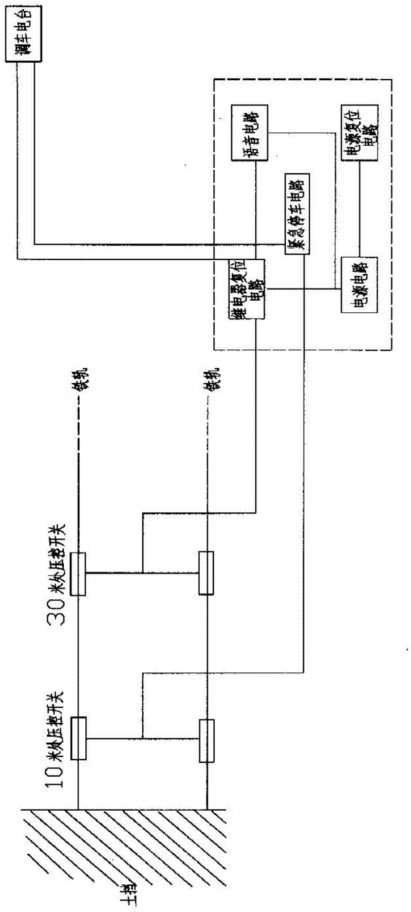
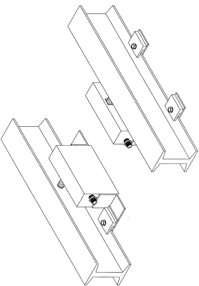
[0018] Depend on Figures 1 to 9 It can be seen that the present invention is composed of a train voltage control switch arranged on the inner side of the train rail, and a controller and a shunting station DT arranged outside the rail, wherein:
[0019] The train voltage-controlled switch is set as No. 1 voltage-controlled switch K1 and No. 2 voltage-controlled switch K2. No. 1 voltage-controlled switch K1 is provided with normally open contacts S1 and S2, and No. 2 voltage-controlled switch K2 is provided with normally open contacts. Points S3 and S4, and the normally open contacts S1 and S2 are connected in series, and the normally open contacts S3 and S4 are connected in series. When the vehicle wheel presses any set of voltage-controlled switches, the normally closed signal is output to the controller.
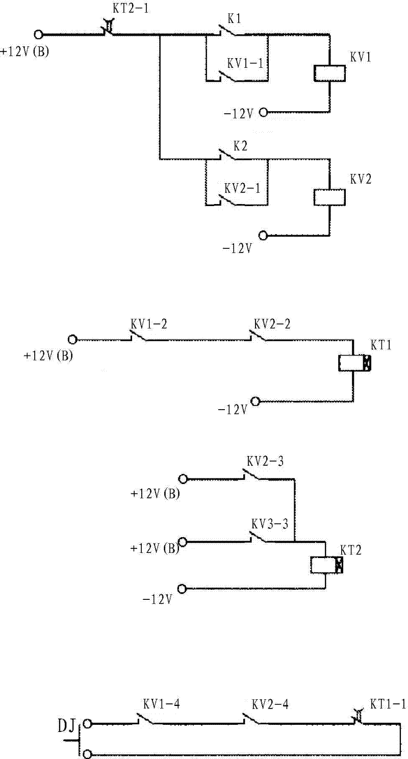
[0020] The described controller arranged outside the rails includes a power supply circuit, an emergency stop signal circuit, a voice circuit, a power reset circuit, a re...
PUM
 Abstract
Description
Claims
Application Information