
Hinged-blade cross-axis turbine for hydroelectric power generation

A technology for hydroelectric generators and turbines, which is used in hydroelectric power generation, reaction engines, water wheels, etc., and can solve the problem that the rotors cannot be closely matched.

Inactive Publication Date: 2012-02-22
水力发电有限公司
View PDF3 Cites 2 Cited by
  • Summary
  • Abstract
  • Description
  • Claims
  • Application Information

AI Technical Summary

Problems solved by technology

[0010] Propeller rotors are round but the water channel is usually rectangular so the rotor does not fit snugly into the channel

Method used


Image

  • Hinged-blade cross-axis turbine for hydroelectric power generation
  • Hinged-blade cross-axis turbine for hydroelectric power generation
  • Hinged-blade cross-axis turbine for hydroelectric power generation

Examples


Embodiment Construction

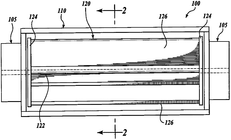
[0026] A hydroelectric generator system 100 according to the present invention is shown in figure 1 middle. In this embodiment, the system 100 includes a water turbine 120 disposed within an optional frame structure 110 . While a simple open (open) rectangular frame structure 110 is illustrated, it is understood that any suitable frame structure may alternatively be used, such as a bifurcated frame including upright supports on either side of the turbine 120 .

[0027] In this embodiment, a pair of generators 105 are attached to either end of the frame structure 110 . Although two generators 105 are shown, it will be appreciated that a different number of generators could alternatively be used. It is believed that in many applications a single generator 105 is preferred.

[0028] New flip-wing TM Turbine 120 is rotatably mounted in frame 110 by a turbine drive shaft 122 configured to driveably engage generator 105 . The turbine 120 includes oppositely disposed support pla...


PUM


Abstract

A power generator comprising a generator drivably attached to a turbine. The turbine comprises a shaft rotatably mounted to a frame. Support plates drivably engage the shaft and a plurality of blades are pivotably connected to the support plates. Each blade has a distal edge that is disposed adjacent the shaft when the blade is pivoted to a stopped position. During operation the blades revolve about the shaft axis. Each blade is held in the stopped position by the flow stream for a portion of the revolution and is pivoted away from the stopped position for the remainder of the revolution. In one embodiment, blade stops limit the outward pivot of the blades to improve efficiency. In another embodiment a second set of blades are provided and rotationally offset from the first blades. In another embodiments the support plates are configured as rotors for the generator.

Description

[0001] Cross References to Related Applications [0002] This application claims the benefit of Provisional Application No. 61 / 162560, filed March 23, 2009, the entire contents of which are hereby incorporated by reference in their entirety. Background technique [0003] For more than six thousand years, devices have been used to harness the energy of moving fluids, such as water and air, for power. For example, water wheels have been used for thousands of years to harness energy from moving water sources for power. According to some sources, the earliest known water turbines date to about the beginning of the fourth century, where a pair of screw turbine milling sites have been found dating to about the beginning of the fourth century. A horizontal water wheel with inclined blades is mounted on the bottom of a water-filled circular shaft so that water from the gutter acts on the submerged (submerged) water wheel to generate power. [0004] The main purpose of a hydro turbin...

Claims


Application Information

Patent Timeline
IPC IPC(8): F03B3/12F03B7/00F03B11/02F03B17/06
CPCF03B17/065F05B2240/40Y02E10/30F03B3/12F03B7/00F03B11/02F03B17/06Y02E10/20
Inventor W·B·哈姆纳
Owner 水力发电有限公司
Features
  • Generate Ideas
  • Intellectual Property
  • Life Sciences
  • Materials
  • Tech Scout
  • Unparalleled Data Quality
  • Higher Quality Content
  • 60% Fewer Hallucinations
Learn More