
Guide nail structure and nail gun with the same

A nail gun and guide nail technology, applied in the direction of nail staple tools, manufacturing tools, etc., can solve the problems of uneven force on the side of the nail needle and affect the performance, so as to improve work efficiency, avoid nail sticking problems, and improve nails. The effect of uneven needle force

Inactive Publication Date: 2014-10-15
APEX MFG
View PDF7 Cites 0 Cited by
  • Summary
  • Abstract
  • Description
  • Claims
  • Application Information

AI Technical Summary

Problems solved by technology

[0004] In other words, the guide pins of the conventional guide nail structure are all designed to pivot. The disadvantage of this is that the guide pins will become inclined when the nail is straightened, so that the side of the nail cannot be fully supported, resulting in uneven force. , which may affect its effectiveness

Method used


Image

  • Guide nail structure and nail gun with the same
  • Guide nail structure and nail gun with the same
  • Guide nail structure and nail gun with the same

Examples


Embodiment Construction

[0031] The structural features and expected effects of the present invention will be described below with reference to preferred embodiments, which should not be used to limit the protection scope of the present invention.

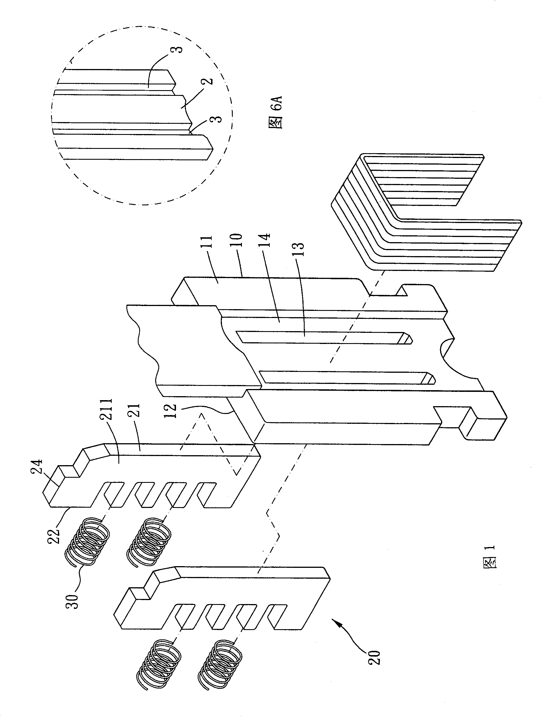
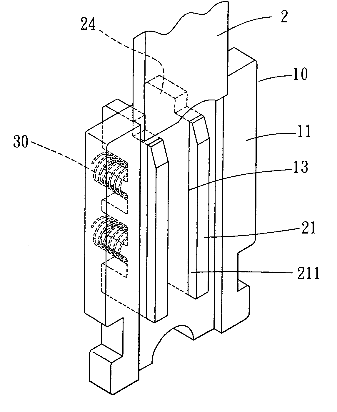
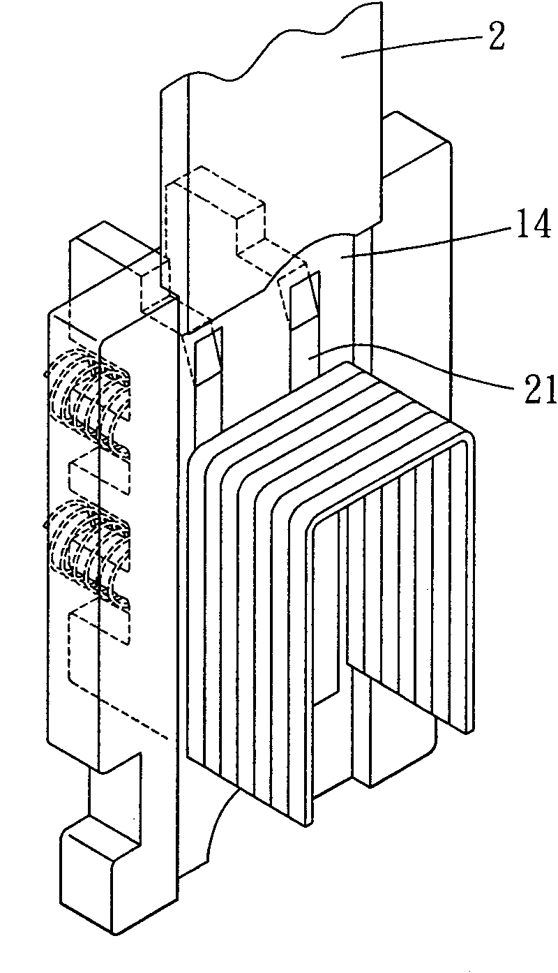
[0032] Please refer to figure 1 and figure 2 . In a preferred embodiment of the present invention, the nail guide structure is provided in a nail gun with a nail rail, and the nail guide structure is provided in front of the nail rail, and the nail guide structure includes a guide plate 10, at least A support piece 20 and a pushing means.

[0033] The guide plate 10 is vertically arranged in front of the nail rail, the guide plate 10 has a first surface 11 and a second surface 12 opposite to the first surface 11, the first surface 11 of the guide plate faces the nail rail, And the guide plate 10 is provided with at least one vertical through groove 13 (in this embodiment, two vertical through grooves are provided), and the through groove 13 runs throug...


PUM


Abstract

The invention discloses a nail guiding structure, comprising a guiding plate, at least one supporting member and a pushing and butting means. The guiding plate is vertically arranged in front of a nail rail and is provided with a first face and a second face, the first face of the guiding plate faces to the nail rail, the guiding plate is provided with at least one vertical penetration groove which penetrates through the first face and the second face of the guiding plate, the supporting member penetrates into the penetration groove in a manner of sliding back and forth, the supporting member is provided with a supporting end and a pushing and butting end, the supporting end selectively protrudes and extends outside the first face, the pushing and butting end is located at the side with the second face, the supporting member is further provided with at least one supporting face which is parallel to the extending direction of the nail rail and is used for supporting and righting a nail pin, and the pushing and butting means is used for elastically pushing and butting the pushing and butting end, and thus, the supporting end is endowed with a trend of protruding and extending to the outside of the first face.

Description

technical field [0001] The invention relates to a nail guide structure and a nail gun with the nail guide structure. Background technique [0002] The nail gun hits the nail with the help of the striker, so that the nail can be nailed into the target to achieve the fixing effect; among them, in order to keep the nail upright when it is fired, or to prevent the nail from being skewed and causing the nail to be jammed, some nail guns will There is a guide nail structure in front of the rail, so that the nail needle can be kept upright for firing. [0003] No. US 5692665 patent discloses a kind of guide nail structure, its figure 1 Disclosed are two guide pins 8, 9, the two guide pins 8, 9 can selectively pivot to the front of the nail rail by using their elastic force, so as to right the nail needle; image 3 It is disclosed that the two guide pins 52 , 62 are pivoted by the pivot 33 , and are pushed against by the shrapnel 70 to pivot toward the nail rail. [0004] In othe...

Claims


Application Information

Patent Timeline
Patent Type & Authority Patents(China)
IPC IPC(8): B25C5/16
Inventor 王景立王荣欲
Owner APEX MFG
Learn More