Full-automatic bedside cabinet

A bedside cabinet, fully automatic technology, applied in the field of bedside cabinets, can solve the problems of inconvenient taking and putting shoes, inconvenient use, and affecting the rest of residents, etc., and achieve the effect of simple structure, prevention of being burned out, and convenient use

Inactive Publication Date: 2012-03-21
NINGBO UNIV
View PDF6 Cites 4 Cited by
  • Summary
  • Abstract
  • Description
  • Claims
  • Application Information

AI Technical Summary

Problems solved by technology

But at present, this bedside cabinet used in hotels is basically a cabinet structure. For the bedside cabinet with cabinet door, when the guest puts the shoes, he needs to open the cabinet door first, then put the shoes, and then close the cabinet door after

Method used


Image

  • Full-automatic bedside cabinet
  • Full-automatic bedside cabinet
  • Full-automatic bedside cabinet

Examples


Embodiment 1

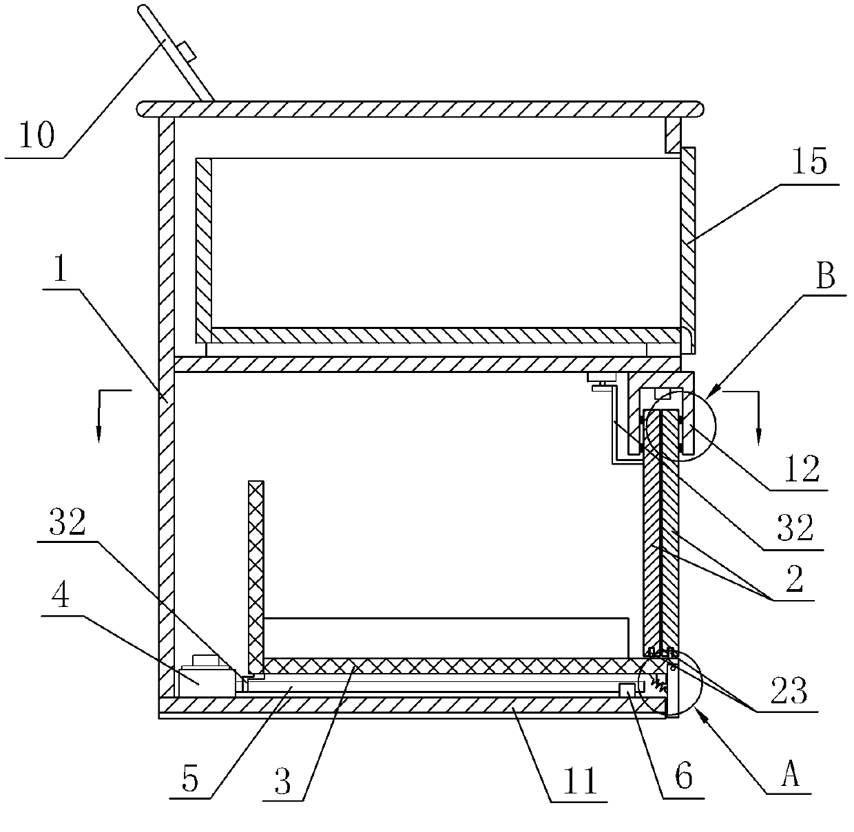
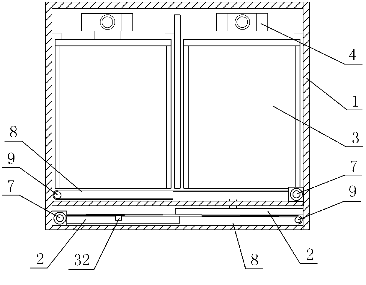
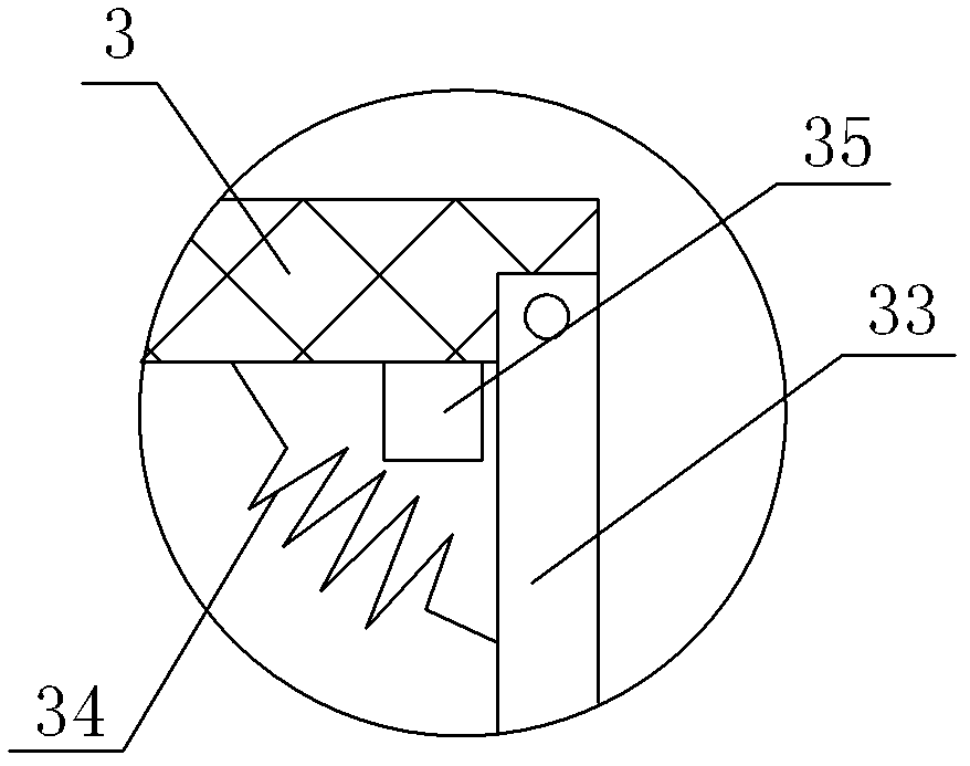
[0021] Embodiment 1: As shown in the figure, a fully automatic bedside table includes a cabinet body 1, two sliding doors 2 and two sets of shoe racks 3 arranged in the cabinet body 1, the positions of the shoe racks 3 and the positions of the sliding doors 2 In one-to-one correspondence, a sliding sleeve 12 is set on the top of the sliding door 2, and the sliding sleeve 12 is fixedly connected to the cabinet body 1, and the side of the upper end of the sliding door 2 is fixedly provided with a first slide rail 21 and a first pulley 22 arranged up and down. The sliding sleeve 12 is fixedly provided with the second pulley 13 and the second slide rail 14 respectively matched with the first slide rail 21 and the first pulley 22, and the lower end of the sliding door 2 is pivotally connected with a roller 23. A shoe rack driving device is connected, and the shoe rack driving device includes a first motor 4, a first belt 5 and a first pulley (not shown in the figure), and the first ...

Embodiment 2

[0022] Embodiment 2: As shown in the figure, other structures are the same as Embodiment 1, the difference is that the second shoe rack limiting device is a first current detection circuit connected to the control system 10, and the first current detection circuit includes a Hall current sensor 41. V / F converter 42, photoelectric isolator 43 and NOT gate 44, Hall current sensor 41 is connected with first motor 4, Hall current sensor 41 is connected with first resistor R1, first resistor R1 is isolated from photoelectricity The input terminal of the V / F converter 43 is connected in parallel, the input terminal of the V / F converter 42 is connected in parallel on the first resistor R1, the output terminal of the V / F converter 42 is connected with the input terminal of the NOT gate 44, and the output terminal of the NOT gate 44 is connected There is a second resistor R2, the second resistor R2 is connected to the input terminal of the photoelectric isolator 43, the output terminal ...

Embodiment 3

[0023] Embodiment 3: As shown in the figure, other structures are the same as Embodiment 2, the difference is that a partition plate 16 is fixedly arranged in the cabinet body 1, and a drawer driving device is arranged on the partition board 16, and the drawer driving device includes a third motor 17. The transmission wheel (not shown in the figure) and the transmission belt 18, the third motor 17 and the transmission wheel (not shown in the figure) are fixedly connected to the partition plate 16 respectively, and the bottom of the drawer 15 is fixedly connected with a connecting piece 19, the connecting piece 19 is fixedly connected with the transmission belt 18, the drawer 15 is slidingly matched with the cabinet body 1, the third motor 17 is electrically connected with the control system 10, the third motor 17 is connected with the second current detection circuit connected with the control system 10, the second current detection circuit The circuit is the same as the first ...


PUM


Abstract

The invention discloses a full-automatic bedside cabinet, which comprises a cabinet body, two sliding doors and two groups of shoe racks which are arranged in the cabinet body. The full-automatic bedside cabinet is characterized in that a sliding sleeve is sheathed on the upper parts of the sliding doors, the sliding sleeve is fixedly connected onto the cabinet body, a first sliding rail and a first sliding wheel which are arranged vertically are fixedly arranged on the side surface of the upper end of one of the sliding doors, a second sliding wheel and a second sliding rail which are respectively matched with the first sliding rail and the first sliding wheel are fixedly arranged on the sliding sleeve, a sliding door driving device is connected onto each sliding door, a shoe rack driving device is connected onto each group of shoe racks, a first shoe rack limiting device is arranged below each group of shoe racks, the first shoe rack limiting device is fixedly arranged on the bottomplate of the cabinet body and a control system is arranged on the cabinet body. The full-automatic bedside cabinet has the advantages that the structure is simple, the device is convenient to use, the sliding doors can be automatically opened or closed under the control of the control system, shoes can be automatically delivered out of the cabinet body or drawn into the cabinet body to facilitateusers to pick or place the shoes and the peculiar smells of the shoes can be prevented from being volatilized into a room.

Description

technical field [0001] The invention relates to a bedside table, in particular to a fully automatic bedside table. Background technique [0002] The bedside cabinets used in hotels and guesthouses are all equipped with a cavity for storing shoes under them, which can be used to put disposable slippers special for hotels, and can also be used to store guests' shoes. But at present, this bedside cabinet used in hotels is basically a cabinet structure. For the bedside cabinet with cabinet door, when the guest puts the shoes, he needs to open the cabinet door first, then put the shoes, and then close the cabinet door after putting the shoes. It is inconvenient; and for the bedside table without a cabinet door, after the guest puts the shoes in the bedside table, the odor from the shoes will affect the rest of the guest, and it is not convenient for the guest to take and put the shoes. Contents of the invention [0003] The technical problem to be solved by the present invent...

Claims


Application Information

Patent Timeline
IPC IPC(8): A47B79/00A47B61/04
Inventor 李国富樊康荣施彦泮周杉
Owner NINGBO UNIV
Why Eureka
Try Eureka