Optoelectronic compound optical cable joint closure and electric cable installation method

An optical cable splice box, photoelectric composite technology, applied in the direction of cable terminal, fiber mechanical structure, etc., can solve problems such as waste, and achieve the effect of solving the difficulty of power extraction

Active Publication Date: 2012-03-21
CHINA MOBILE GRP GUANGDONG CO LTD +1
View PDF3 Cites 5 Cited by
  • Summary
  • Abstract
  • Description
  • Claims
  • Application Information

AI Technical Summary

Problems solved by technology

[0003] The invention provides a photoelectric composite optical cable splice box, which connects optical cables and cables together, thereby solving the technical problem that is easy to cause waste in the prior art

Method used


Image

  • Optoelectronic compound optical cable joint closure and electric cable installation method
  • Optoelectronic compound optical cable joint closure and electric cable installation method
  • Optoelectronic compound optical cable joint closure and electric cable installation method

Examples


Embodiment Construction

[0010] Specific embodiments of the present invention are described with reference to the above drawings.

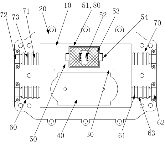
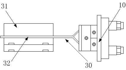
[0011] Depend on figure 1 with figure 2 As can be seen in the figure, this photoelectric composite optical cable splice box includes an upper cover 10 and a bottom box 20 fastened with the upper cover 10, and a bottom box 20 fixed to the bottom box 20 is arranged in the hollow space formed by the fastening of the upper cover 10 and the bottom box 20. The photoelectric isolation board 30 on the top, the optical cable fusion module 40 and the cable joint module 50 fixed on the photoelectric isolation board 30 also include an optical cable channel 60 and a cable channel 70 arranged on the upper cover 10, and the optical cable channel 60 communicates with the optical cable The welding module 40 , the cable channel 70 is connected to the cable joint module 50 . In the present invention, the connection of the optical cable and the cable is concentrated in one photoelectric c...


PUM


Abstract

The invention discloses an optoelectronic compound optical cable joint closure, which comprises an upper cover (10), a bottom closure (20), an optoelectronic isolation board (30), an optical cable welding module (40), an electric cable joint module (50), an optical cable path (60) and an electric cable path (70), wherein the upper cover and the bottom closure are opened, the optical cable and the electric cable are penetrated in from the optical cable path and the electric cable path, and butt joint optical fibers are subjected to thermal welding to become a whole. In the optoelectronic compound optical cable joint closure, according to the mature optical fiber thermal welding technology and the shunting joint technology of the electric cable, the node of a circuit joint and a light path is innovatively arranged in the middle of the optical cable joint closure, a node through connection guarantee is provided while light and electricity are provided for network terminal equipment, the defects of multiple constructions of contact separation because the traditional optical fiber network and the traditional power grid are separately erected can be solved, and the problem that the network terminal equipment is difficult to take electricity can be better solved.

Description

technical field [0001] The invention relates to optical cable transmission, in particular to a joint device and an installation method for optical cable connection. Background technique [0002] In the prior art, the optical cable and the electric cable are connected separately, each has its own connecting device, and requires multiple constructions. This method of separate erection is bound to cause waste of manpower, material and financial resources, and it is also easy to cause network terminal equipment to be damaged. Difficulty getting electricity, etc. Contents of the invention [0003] The invention provides a photoelectric composite optical cable joint box, which connects optical cables and electric cables in a centralized manner, thereby solving the technical problem of easy waste in the prior art. [0004] The photoelectric composite optical cable splice box provided by the present invention to solve the above-mentioned technical problems includes an upper cover...

Claims


Application Information

Patent Timeline
Patent Type & Authority Applications(China)
IPC IPC(8): G02B6/44H02G15/06
Inventor 刘奕安魏杰危加强郭建民沙和鸣
Owner CHINA MOBILE GRP GUANGDONG CO LTD
Why Eureka
Try Eureka