An electric window actuator

A technology of electric mechanism and executive mechanism, which is applied in the direction of power control mechanism, wing leaf control mechanism, door/window accessories, etc. It can solve the problems of window damage, waste of resources, and affecting the appearance of warehouses, etc., and achieves convenient installation and use, and extended Good service life and market prospect

Active Publication Date: 2018-03-02
河南西城电子科技有限公司
View PDF3 Cites 0 Cited by
  • Summary
  • Abstract
  • Description
  • Claims
  • Application Information

AI Technical Summary

Problems solved by technology

[0004] 1. Install electric push rods on the windows, such as the Chinese patent application with the patent number "201520556868.X", which uses electric push rods and solar power supply. Although the structure is simple, it requires a lot of changes to the windows, and even requires the entire Window replacement is time-consuming, labor-intensive and wastes resources;
[0005] 2. Do not change the window, but only add a motor to the original window opening handle to open, but often due to unreasonable structure, either the window switch is not strict or the window cannot be controlled accurately, and the window is damaged. More importantly, the electric control is carried out. It is necessary to take electricity; for example, the Chinese patent application with the patent number "201510236957.0" communicates and connects through the CAN bus. The layout of the lines is huge and affects the beauty of the warehouse, and the cost is very high;
[0006] 3. There are also electric windows opened by remote control. For example, the Chinese patent application with the patent number "200920277196.3" requires manual control of the remote control to open or close the windows. The windows cannot be opened or closed automatically, but in the granary area with many windows, If all need remote control, it is a waste of manpower and material resources

Method used


Image

  • An electric window actuator

Examples


Embodiment Construction

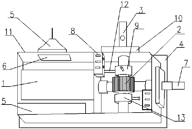
[0024] Such as figure 1 As shown, the present invention discloses an electric window actuator, including a wireless receiving module, an electric mechanism 1 arranged in a box body 11, a transmission mechanism, a limit mechanism, and a window opening mechanism 3 arranged outside the box body, The solar panel 4, wherein the solar panel 4 is a 16V / 5W model, the solar panel 4 charges the converted electric energy into the storage battery 5 through the charge and discharge control circuit, and the storage battery 5 uses a 12V lithium battery to supply power to various mechanisms and modules.

[0025] The electric mechanism includes a stepping motor and a reducer, and the transmission mechanism includes a variable speed worm gear 2, the input end of the variable speed worm wheel 2 is arranged in cooperation with the output shaft of the electric mechanism 1, and the output shaft of the variable speed worm wheel 2 is connected to the window opening. Body 3 connection. Among them, th...


PUM


Abstract

The invention discloses an electric window performing mechanism which comprises a wireless receiving and dispatching module, an electric mechanism arranged in a box body, a transmission mechanism and a limiting mechanism as well as a window opening mechanism and a solar panel arranged outside the box body; the solar panel is used for charging converted electric energy into a storage battery through a charging and discharging control circuit; the storage battery supplies power to each mechanism and the module through the control circuit; the wireless receiving and dispatching module is used for receiving an instruction and transmitting the instruction to an electric mechanism control circuit; the electric mechanism control circuit controls an electric mechanism to act; the transmission mechanism drives the window opening mechanism to act; and the limiting mechanism is arranged on the transmission mechanism. The electric window performing mechanism does not need to arrange wires from a monitoring platform to a window body, but automatically receives the instruction of a monitoring platform to automatically open or close the window by virtue of the electric mechanism and the transmission mechanism, so that mounting and use are convenient.

Description

technical field [0001] The invention belongs to the technical field of electric windows, in particular to an electric window actuator. Background technique [0002] In recent years, with the development of science and technology, wisdom has become a hot topic. Smart grain depots have been born from the environment of smart cities. While deploying a large number of sensors in the depot area, it is also necessary to monitor the facilities that were originally manually operated. Granary windows are a typical case of electrification transformation. [0003] At present, there are many ways to realize electric window opening in the market, and there are roughly the following ways: [0004] 1. Install electric push rods on the windows, such as the Chinese patent application with the patent number "201520556868.X", which uses electric push rods and solar power supply. Although the structure is simple, it requires a lot of changes to the windows, and even requires the entire Window...

Claims


Application Information

Patent Timeline
Patent Type & Authority Patents(China)
IPC IPC(8): E05F15/77E05F15/611E05F15/40H02J7/35
CPCE05F15/40E05F15/611E05F15/77E05Y2900/148H02J7/35
Inventor 胡学润
Owner 河南西城电子科技有限公司
Why Eureka
Try Eureka