
Bracket with adjustable rotating angle

A technology of rotation angle and ball socket, applied to the parts of lighting devices, lighting devices, lighting auxiliary devices, etc., can solve the problems of unadjustable brackets, cumbersome operation, and limited lighting direction of lamps 15, achieving high degree of freedom and adjustment easy effect

Active Publication Date: 2013-01-09
上海康耐司信号设备有限公司
View PDF10 Cites 0 Cited by
  • Summary
  • Abstract
  • Description
  • Claims
  • Application Information

AI Technical Summary

Problems solved by technology

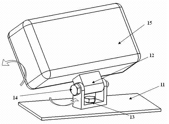
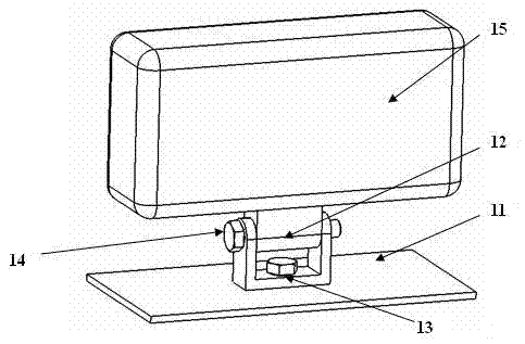
Its disadvantage is that the lamp bracket 1 in the prior art needs to adjust two screws to adjust the horizontal and vertical directions respectively, and the operation is cumbersome; at the same time, the direction adjustment mechanism of the existing lamp bracket 1 is usually provided with a minimum adjustment angle, so that the bracket cannot be adjusted to any position. direction, which limits the lighting direction of the lamp 15

Method used


Image

  • Bracket with adjustable rotating angle
  • Bracket with adjustable rotating angle
  • Bracket with adjustable rotating angle

Examples


Embodiment Construction

[0025] The specific implementation manners of the present invention will be described below in conjunction with the accompanying drawings.

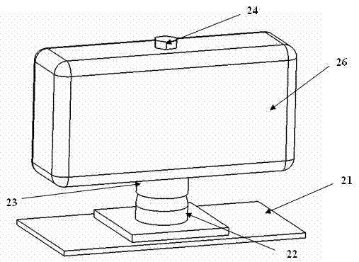
[0026] like image 3 As shown, the present invention describes a bracket with adjustable rotation angle, the bracket includes a mounting plate 21 disposed on the bottom, a ball socket base 22 disposed on the mounting plate 21, a lamp base disposed on the ball socket base 22 23, and the mounting screw 24 sleeved in the lamp base 23, the lamp 26 is fixed on the lamp base 23.

[0027] like Figure 4 As shown, the mounting plate 21 is a flat plate, which is fixed on any plane and serves as the mounting base of the bracket. The ball-and-socket base 22 is fixed on the above-mentioned mounting plate 21 , and the bottom of the ball-and-socket base 22 is set as a plane. The central protrusion of the ball socket base 22 is configured as a convex hemispherical structure, and an inner cavity 222 is formed between the hemispherical structure and th...


PUM


Abstract

The invention provides a bracket with an adjustable rotating angle. The bracket is characterized by comprising a mounting plate, a ball socket base, a mounting screw, a hemispherical nut and a lamp pedestal, wherein the ball socket base is arranged on the mounting plate; the top of the ball socket base is convexly hemispherical and provided with an opening; a cavity is formed between the mountingplate and the ball socket base; the hemispherical nut is sleeved at one end of the mounting screw; the hemispherical nut is adapted with the inner wall of the ball socket base; the lamp pedestal is provided with a through hole; the lamp pedestal is sleeved on the mounting screw through the through hole; the bottom of the lamp pedestal is concavely hemispherical and adapted with the top of the ball socket base; and the hemispherical nut is arranged in the cavity through the opening. A lamp is fixed in a manner of pressing the ball socket base with the hemispherical nut and the lamp pedestal; and when the lamp is fixed, the illumination direction of the lamp can be adjusted at a random angle within a certain range by adjusting one screw, and the lamp has no minimum adjusted angle.

Description

technical field [0001] The invention relates to an adjustable bracket suitable for lighting equipment, in particular to a bracket with adjustable rotation angle. Background technique [0002] At present, in order for the lamps to adapt to different installation conditions, achieve different irradiation angles, and make the lamps have a wider range of use, it is often necessary to adjust the installation angle or installation position of the lamps when using the lamps to obtain better lighting angles and lighting effects. . Therefore, it is the best choice to install a bracket on the lamp that can adjust the rotation angle of the lamp. [0003] like figure 1 As shown, it is the basic structure of the conventional lamp bracket 1 in the prior art, which includes a mounting surface 11 fixed on any plane, a vertical mounting screw 13 fixed on the mounting surface 11, and a vertical mounting screw 13 fixed on the mounting surface 11. The bracket 12 on the top, the horizontal mo...

Claims


Application Information

Patent Timeline
Patent Type & Authority Patents(China)
IPC IPC(8): F21V21/116
Inventor 程其政潘方亮
Owner 上海康耐司信号设备有限公司
Learn More