Anchoring harpoon, for example for an aircraft, and anchoring system including one such harpoon

An anchoring fork and anchoring technology are applied in the field of anchoring forks

Active Publication Date: 2012-04-04
DCNS SA
View PDF6 Cites 5 Cited by
  • Summary
  • Abstract
  • Description
  • Claims
  • Application Information

AI Technical Summary

Problems solved by technology

[0010] In fact, these studies show that there are problems with size, energy, maintenance, etc.

Method used


Image

  • Anchoring harpoon, for example for an aircraft, and anchoring system including one such harpoon
  • Anchoring harpoon, for example for an aircraft, and anchoring system including one such harpoon
  • Anchoring harpoon, for example for an aircraft, and anchoring system including one such harpoon

Examples


Embodiment Construction

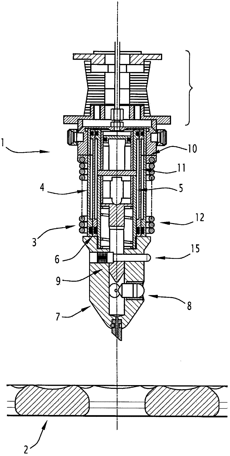
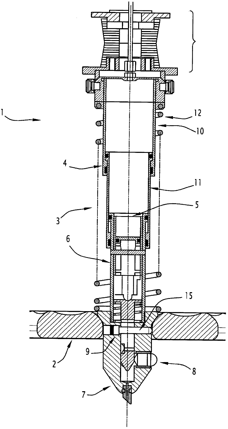
[0030] In fact these graphs are especially figure 1 and 2 Anchor prongs are shown especially for use with aircraft on platforms of the warship type or other.

[0031] The aircraft may for example be a rotary wing drone.

[0032] The fork, indicated generally by reference number 1 in the figures, is adapted to cooperate with the anchoring grid of the platform, generally indicated by reference number 2 in these figures.

[0033] In fact, the fork has a jack, indicated generally at 3 , comprising a cylinder 4 in which a piston 5 can move.

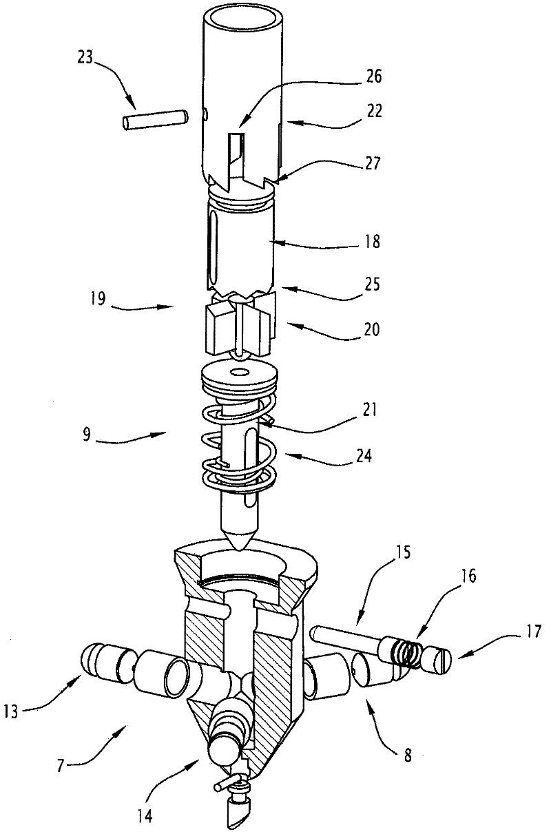
[0034] These pistons are provided with a rod 6 extending beyond the cylinder, the free end of which has a prong hooked into the grid, which prong is indicated as part 7 .

[0035] In fact, as described in the aforementioned prior art document, the prongs are provided with retaining fingers intended to be retained in the grating, which are radially movable between a retracted position and an active position by control means, as will be descr...


PUM


Abstract

The invention relates to an anchoring harpoon (1) intended in particular for an aircraft, capable of cooperating with an anchoring grate (2) of a platform, comprising jack means (3) including cylinder means (4) containing mobile piston means (5) provided with a rod (6) that extends beyond the cylinder means, the free end of which includes a harpoon head (7) that is hooked in the grate and comprises retaining fingers (8, 13, 14) that can be moved between a retracted position and an active position by control means (9). The invention is characterised in that the jack means are connected to a pressurised fluid source (30) by means of control means (31) and in that the pressurised fluid source includes a consumable gas cartridge (30).

Description

technical field [0001] The invention relates to an anchoring fork, in particular for aircraft, capable of cooperating with an anchoring grid of a platform, and to an anchoring system comprising such a fork. Background technique [0002] Such forks and anchoring systems are already known in the prior art. [0003] For example FR-A-2701689 describes a fork for equipping a rotorcraft such as a helicopter, which can be pulled towards the landing platform of a ship so that the prongs are fixed on the grid, thereby forming the aircraft's Anchor points, especially for its landing maneuvers. [0004] The anchoring fork described in this document has a cylinder part in which a piston part moves, the piston part being provided with a rod extending beyond the cylinder part, the free end of which comprises a prong hooked in a grid. The prong is in fact provided with retaining fingers for retaining in the grid, which can be moved radially between a retracted position and an active posi...

Claims


Application Information

Patent Timeline
Patent Type & Authority Applications(China)
IPC IPC(8): B64F1/12F16B21/16
CPCB64F1/16F16B21/16B64F1/125B64U70/30B64C39/024B64F1/12
Inventor 罗南·阿弗尔德圣罗姆
Owner DCNS SA
Why Eureka
Try Eureka