
Terminal post for a barrier and a barrier

An obstacle and pillar technology, which is applied to the terminal pillar for obstacles and the field of obstacles, can solve problems such as expensive and time-consuming

Active Publication Date: 2012-04-11
VALMONT HIGHWAY TECH
View PDF10 Cites 1 Cited by
  • Summary
  • Abstract
  • Description
  • Claims
  • Application Information

AI Technical Summary

Problems solved by technology

In contrast, the terminal strut detailed in WO2007 / 129915, while effectively serving its purpose, requires a separate anchoring body to be fabricated and attached to the upright member of the terminal strut, which is relatively time consuming and expensive

Method used


Image

  • Terminal post for a barrier and a barrier
  • Terminal post for a barrier and a barrier
  • Terminal post for a barrier and a barrier

Examples


Embodiment Construction

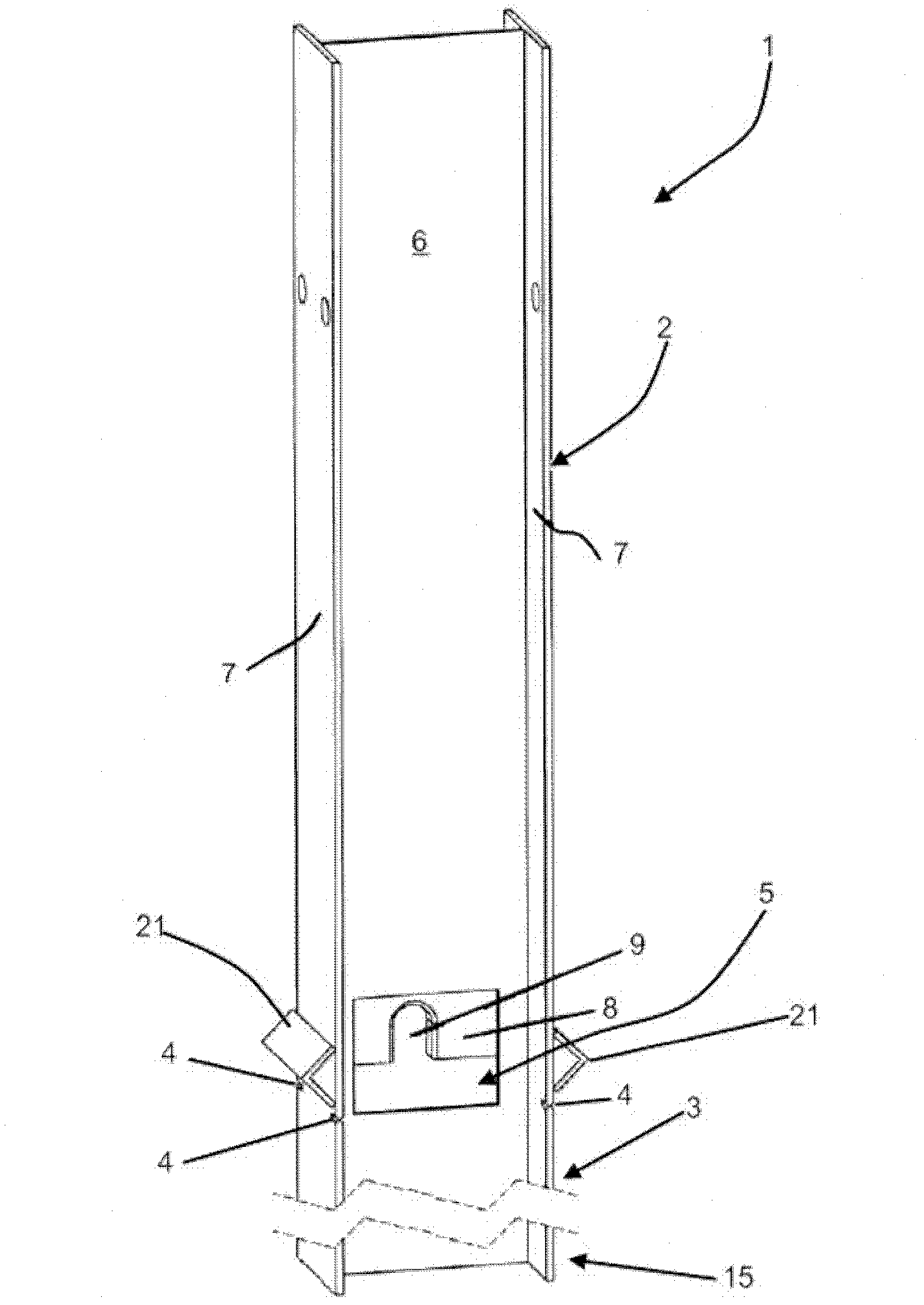
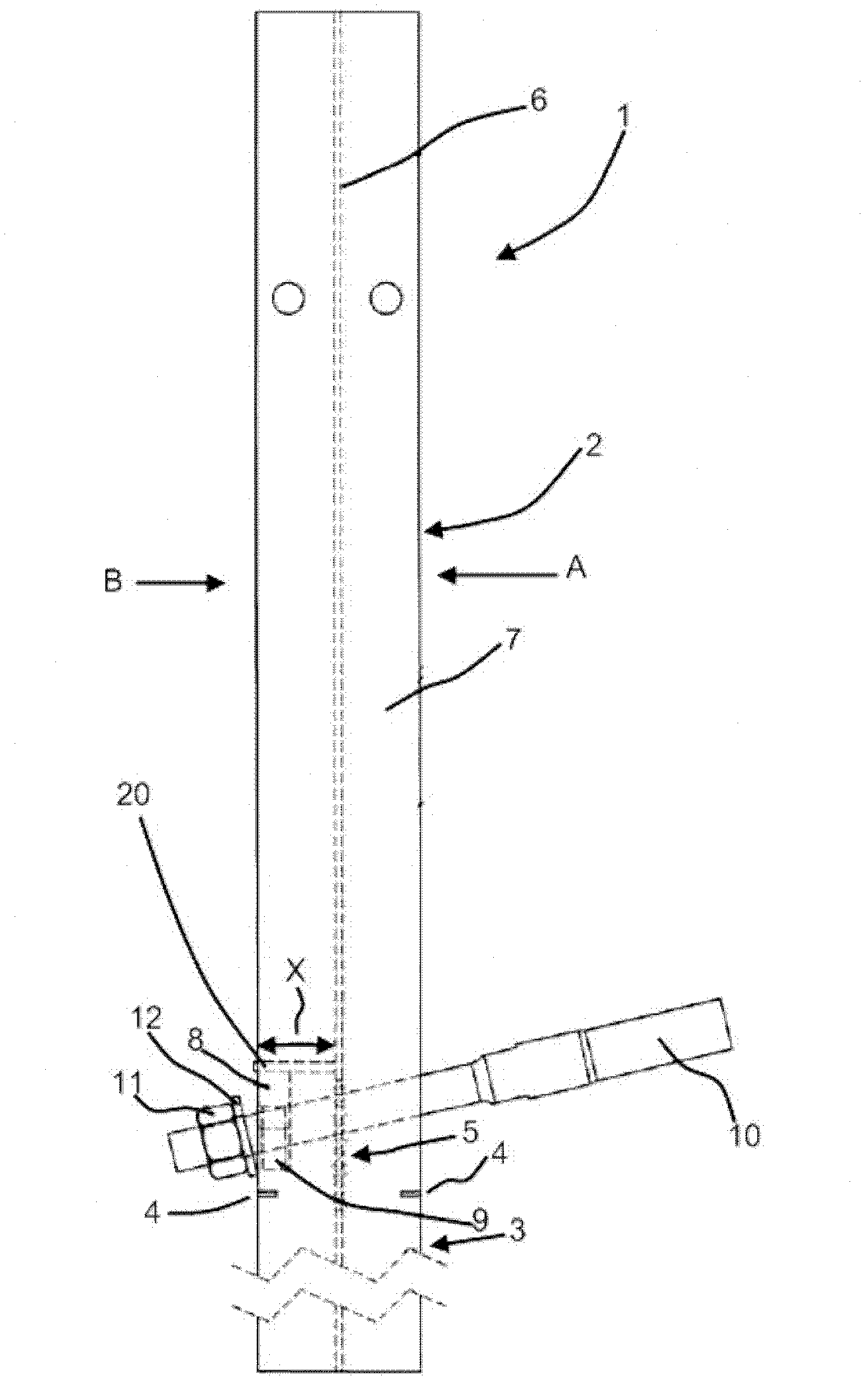
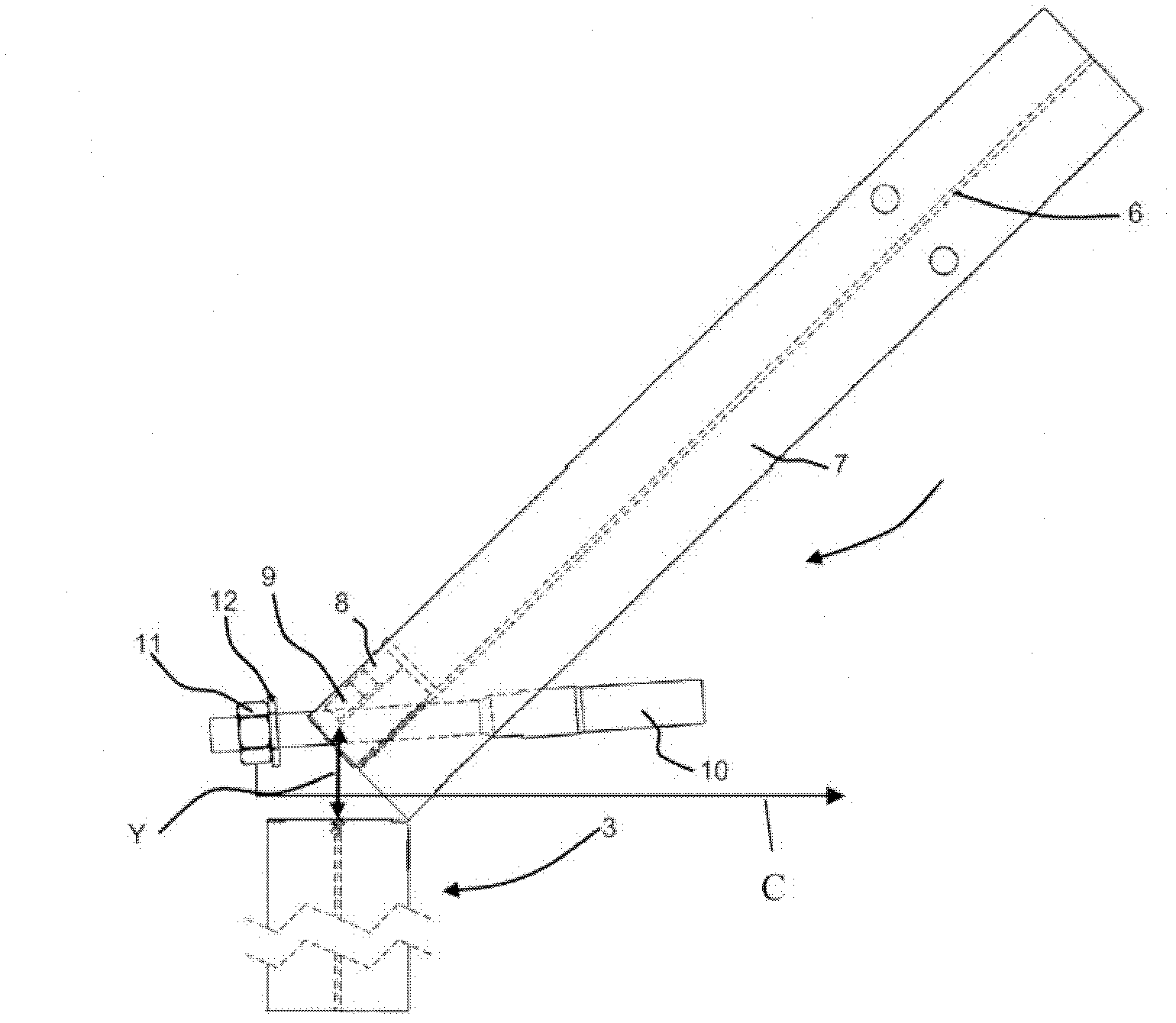
[0042] With respect to the figures, there is provided a terminal post generally indicated by arrow 1 having an upright portion 2 formed of a length of I-beam which, in use, is positioned on the ground. The strut 1 also has a ground engaging portion 3 at one end thereof. The ground engaging portion 3 is generally anchored in the ground (not shown). The ground engaging portion extends from one end 15 of the strut 1 to a point below two pairs of notches 4, one on each side flange 7, both level with the same horizontal plane.

[0043] The uprights 2 have holes 5 positioned in connecting webs 6 that span between side flanges 7 . A transverse stiffening member 8 is positioned on one side of the hole 5 with a slot 9 therein. The slot 9 receives the terminal end of an anchoring rope 10 having a nut 11 and a washer 12 thereon.

[0044] The transverse stiffener 8 is separated from the web 6 by a distance indicated by the double-headed arrow X via a horizontal support member 20 . The...


PUM


Abstract

The present invention relates to a terminal post for a barrier wherein the post includes: - an upright portion; characterised in that the upright portion has an aperture positioned, so that in use: the aperture is located in a region of the upright portion above a ground engaging portion of the upright portion; and wherein located on one side of the aperture is a transverse reinforcing member which includes a slot for receiving a cable; and wherein there is at least one groove, or pair of notches located beneath the aperture, which form(s) a predetermined fail line, along which the post will deform, upon receiving a substantially inline impact, which causes the transverse member to move so as to release said cable, and wherein the aperture is dimensioned to allow the terminal end of the cable formally retained by the slot to pass therethrough.

Description

[0001] Description of the corresponding application [0002] This application is based on a provisional specification filed in relation to New Zealand Patent Application No. 587732, the entire contents of which are hereby incorporated by reference. technical field [0003] The present invention relates to improvements in and relating to struts. In particular, struts for road barriers or other impact environments. Background technique [0004] The invention has particular application to terminal posts in cable barriers. However, the invention can also be used in other environments where the rope is held in tension and it is desirable to be able to release the rope in the event the strut is deformed by impact. [0005] For ease of reference only, the present invention will now be described in relation to ropeway obstacles. [0006] Terminal struts that release the rope in the event of a vehicle impact are well known. [0007] The applicant has previously designed an improv...

Claims


Application Information

Patent Timeline
Patent Type & Authority Applications(China)
IPC IPC(8): E01F15/06
CPCE01F15/143E01F15/00E01F15/06E04H17/20E04H17/04
Inventor 达拉斯·雷克斯·詹姆斯
Owner VALMONT HIGHWAY TECH
Learn More