Hydraulic station for feeding trolley

A technology of feeding trolley and hydraulic station, which is applied in the direction of fluid pressure actuators, conveyors, servo motors, etc., and can solve the problems of inaccurate control of feeding device feeding, feeding device stuck on the track, low production efficiency, etc. , to achieve the effect of simple structure, good self-priming performance and light weight

Inactive Publication Date: 2013-09-04
大连维乐液压制造有限公司
View PDF8 Cites 0 Cited by
  • Summary
  • Abstract
  • Description
  • Claims
  • Application Information

AI Technical Summary

Problems solved by technology

[0002] In the prior art, the structure of the feed hydraulic station system is complicated, and the feeding device cannot be accurately controlled to feed the material. It is easy to cause the feeding device to be stuck on the track during the feeding process, and the production efficiency is low.

Method used


Image

  • Hydraulic station for feeding trolley
  • Hydraulic station for feeding trolley
  • Hydraulic station for feeding trolley

Examples


Embodiment Construction

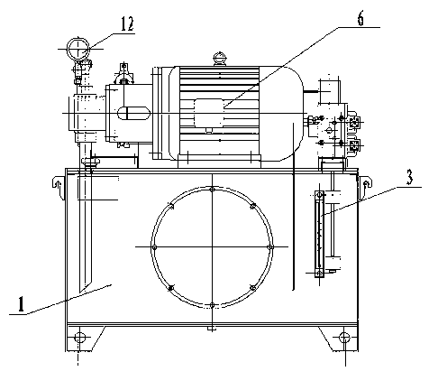
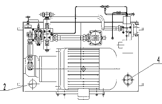
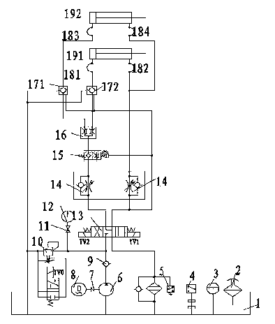
[0014] like figure 1 , figure 2 and image 3 As shown, the feeding trolley hydraulic station is mainly composed of a motor pump group, an executive cylinder, a control valve group and auxiliary devices. Collector valve 16, hydraulic control check valve 171, 172, electromagnetic overflow valve 10 and pipe check valve 9, auxiliary devices include fuel tank 1, air filter 2, liquid level gauge 3, liquid level controller 4, Oil return filter 5, elastic coupling 7, motor 8, shockproof pressure gauge 12 and 4 high-pressure hose joints 181, 182, 183, 184, motor pump unit, control valve group, liquid level controller 4, air filter The cleaner 2 and the oil return filter 5 are arranged on the top of the oil tank 1, the liquid level gauge 3 is arranged on the side of the oil tank 1, the motor 8 is connected with the motor pump unit through the elastic coupling 7, and two executive oil cylinders 191, 192 They are respectively connected to the control valve group through 4 high-pressur...


PUM


Abstract

The invention discloses a hydraulic station for a feeding trolley, which mainly comprises a motor pump unit, an actuating oil cylinder, a control valve group and an auxiliary device. The control valve group comprises an electromagnetic directional valve, a stacked unidirectional throttle valve, a balanced valve, a flow distributing and collecting valve, a hydraulic operated check valve, an electromagnetic relief valve and a tubular check valve. The auxiliary device comprises an oil tank, an air filter, a liquid indicator, a liquid level controller, a return oil filter, an elastic coupler, a motor, a shock-proof pressure gage and a high-pressure hose connector. The motor pump unit, the control valve group, the liquid level controller, the air filter and the return oil filter are arranged at the top of the oil tank, the liquid indicator is arranged on one side of the oil tank, the motor is connected with the motor pump unit through the elastic coupler, and the actuating oil cylinder is connected with the control valve group through the high-pressure hose connector. By the aid of the hydraulic station for the feeding trolley, normal operation of the feeding device is realized, production efficiency is improved, and the problem that the feeding device previously is frequently jammed on a rail due to asynchronism of two cylinders is solved.

Description

technical field [0001] The invention relates to a feeding trolley hydraulic station. Background technique [0002] In the prior art, the structure of the feed hydraulic station system is complicated, and the feeding device cannot be accurately controlled to feed the material, and it is easy to cause the feeding device to be stuck on the track during the feeding process, and the production efficiency is low. Contents of the invention [0003] The object of the present invention is to provide a hydraulic station for feeding trolleys with compact structure and reasonable layout. [0004] The technical scheme adopted by the present invention to achieve the above purpose is: a feeding trolley hydraulic station, mainly composed of a motor pump group, an executive oil cylinder, a control valve group and auxiliary devices. The control valve group includes an electromagnetic reversing valve, a stacking One-way throttle valve, balance valve, diverter and flow valve, hydraulic contr...

Claims


Application Information

Patent Timeline
Patent Type & Authority Patents(China)
IPC IPC(8): B65G35/00F15B11/16
Inventor 段树平丁维力
Owner 大连维乐液压制造有限公司
Why Eureka
Try Eureka