
Etching method and system

An etching system and main etching technology, applied in electrical components, semiconductor/solid-state device manufacturing, circuits, etc., can solve problems such as large CD, metal layer etching residue, etc.

Active Publication Date: 2014-01-22
CSMC TECH FAB2 CO LTD
View PDF4 Cites 0 Cited by
  • Summary
  • Abstract
  • Description
  • Claims
  • Application Information

AI Technical Summary

Problems solved by technology

In this way, after the etching stop point, the actual overetching time is less than the normal overetching time, that is, the thickness of the metal layer etched during the entire etching process is actually less than the normal etching thickness. In this case, It is often easy to cause etching residues on the metal layer, or the CD (critical dimension) of the device is too large and other adverse consequences

Method used


Image

  • Etching method and system
  • Etching method and system

Examples


Embodiment 1

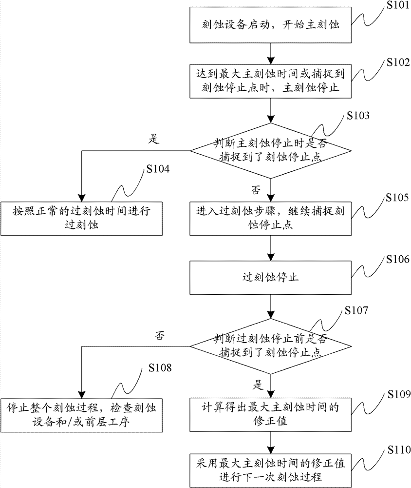
[0045] Based on this, the first embodiment provides an etching method, the flow chart of the method is as follows figure 1 shown, including the following steps:

[0046] Step S101: start the etching equipment, and start main etching;

[0047] Step S102: When the maximum main etching time is reached or the etching stop point is captured, the main etching stops;

[0048] Step S103: After the main etching is stopped, it is judged whether the etching stop point is captured when the main etching is stopped, if yes, go to step S104, if not, go to step S105;

[0049] It should be noted that the purpose of adding this judgment step in this embodiment is to determine whether the initially set maximum main etching time is sufficient to capture the etching stop point, and to lay a foundation for whether the maximum main etching time needs to be extended later.

[0050]Step S104: If the main etching stops at the etching stop point, it means that the set maximum main etching time is enou...

Embodiment 2

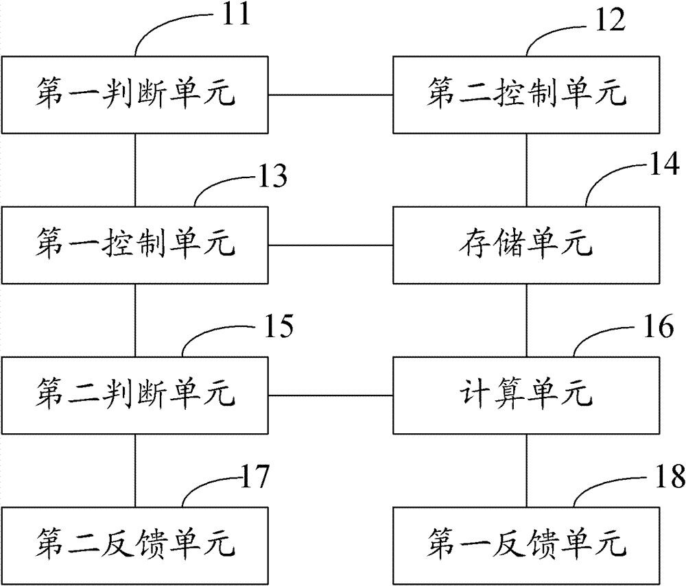
[0075] Corresponding to the method embodiment, this embodiment discloses an etching system, the structural diagram of which is as follows figure 2 As shown, the system includes:

[0076] The first judging unit 11 is configured to judge whether the etching stop point is captured when the main etching stops after the main etching stops;

[0077] The first control unit 13 is used to control the etching equipment to enter over-etch and continue to capture the etch stop point when the main etching stop point is not captured. Automatically stop when the maximum over-etching time is set, and automatically stop when the normal over-etching time has passed after the etching stop point is captured;

[0078] The second judging unit 15 is used to judge whether the etching stop point is captured before the over-etching is stopped after the over-etching is stopped;

[0079] The calculation unit 16 is used to obtain the correction value of the maximum main etching time according to the et...


PUM


Abstract

The invention discloses an etching method and an etching system, wherein the method comprises the following steps of: after main etching is stopped, judging whether etching stopping points are caught when the main etching is stopped, and if not, entering an over-etching step for continuously catching the etching stopping points; when the over-etching step reaches the preset maximum over-etching time, after the etching stopping points are caught and normal over-etching time is passed, automatically stopping; after the over etching is stopped, judging whether etching stopping points are caught or not before the over etching is stopped, and if so, obtaining a correction value of the maximum main etching time according to the etching thickness and the maximum main etching time; and adopting the correction value of the maximum main etching time to carry out next-time etching process. According to the embodiment of the invention, by the introduction of a judgment mechanism and a time feedback mechanism and control for the etching mode of etching equipment, the problems of the etching residual and slightly-large device CDs (Compact Discs) and the like after over-etching due to over-early stopping of the main etching in the prior art are solved.

Description

technical field [0001] The present invention relates to the technical field of semiconductor manufacturing, and more specifically relates to an etching method and system. Background technique [0002] With the rapid development of ultra large scale integration (ULSI, Ultra Large Scale Integration), the manufacturing process of integrated circuits has become more and more complex and refined, and the requirements for etching effects have become more and more stringent. At present, the etching steps in the production process of semiconductor devices are generally divided into two steps: main etching and over-etching. If the main etching time has not yet found the etching stop point, the main etching will also be stopped, and then the over-etching will be performed with a fixed etching time to avoid etching residues. [0003] However, the above-mentioned etching method in the prior art often produces etching residues, and the following takes the etching process of the metal la...

Claims


Application Information

Patent Timeline
Patent Type & Authority Patents(China)
IPC IPC(8): H01L21/00H01L21/02
Inventor 胡骏李健
Owner CSMC TECH FAB2 CO LTD
Learn More