A storage chamber cover and a cloth bonding apparatus

A storage room, cloth bonding technology, applied in the field of storage room cover, can solve the problem of difficult opening and closing of heat-resistant gloves, and achieve the effect of safe installation

Active Publication Date: 2012-07-04
BROTHER KOGYO KK
View PDF5 Cites 0 Cited by
  • Summary
  • Abstract
  • Description
  • Claims
  • Application Information

AI Technical Summary

Problems solved by technology

Therefore, it is difficult for the operator to open and close the cover while wearing heat-resistant gloves.

Method used


Image

  • A storage chamber cover and a cloth bonding apparatus
  • A storage chamber cover and a cloth bonding apparatus
  • A storage chamber cover and a cloth bonding apparatus

Examples


Embodiment Construction

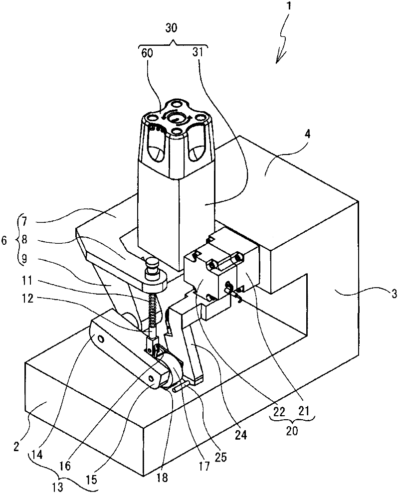
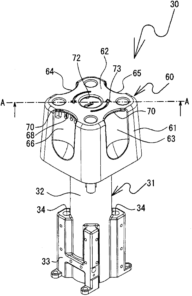
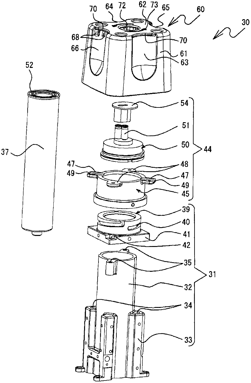
[0022] Next, a storage chamber cover 60 according to an embodiment of the present invention and a cloth bonding apparatus 1 including the storage chamber cover 60 will be described with reference to the drawings.

[0023] refer to figure 1 , the structure of the cloth bonding apparatus 1 will be described. Will figure 1 Right obliquely lower, left obliquely upper, right obliquely upper, and left obliquely lower as the front, rear, right, and left of the cloth bonding apparatus 1, respectively. The cloth bonding apparatus 1 includes a base portion 2 , a column portion 3 , and an arm portion 4 . The base portion 2 is fixed to a table (not shown). The column part 3 extends vertically upward from the right end of the base part 2 . The arm part 4 is connected to the upper end of the column part 3 and protrudes toward the left side of the left side of the column part 3 .

[0024] The base unit 2 includes a lower feed roller, a lower feed motor, and the like (not shown) inside. ...


PUM


Abstract

To provide a storage chamber cover that reliably seals a storage chamber storing an adhesive and that can be mounted and removed easily and safely, and a cloth bonding apparatus that is provided with the storage chamber cover. A screw cover is mounted onto an opening portion of the storage chamber. The storage chamber cover is provided with a tube portion having a recessed portion and covering an outer circumference of the storage chamber, a top wall being formed on an opening in the tube portion, and a cover fixing portion fixing a screw cover on an inner side of the tube portion, in a state in which an axis of rotation of the screw cover and a central axis of the tube portion are parallel to one another. The tube portion is provided with a recessed part recessed toward the inner side. The cylinder part is provided with a recessed part recessed toward the inner side downwards.

Description

technical field [0001] The present invention relates to a storage chamber cover attached to an adhesive storage chamber and a cloth bonding apparatus including the storage chamber cover. Background technique [0002] The cloth bonding device does not sew cloth with needles and sutures, but uses adhesives to bond cloth to cloth. The cloth bonding device includes a storage chamber and a nozzle. The storage chamber stores the adhesive, and heats the stored adhesive to melt. The nozzle sprays out the adhesive melted by the storage chamber, and makes it adhere between the cloths. The cloth bonding device presses cloth and cloth to bond them. Since the bonded cloth does not use stitches, there will be no unevenness on the cloth. [0003] Japanese Patent Laid-Open No. 222764 2010 discloses the structure of a cloth bonding device and a storage chamber. This cloth bonding device increases the air pressure in the storage chamber to press out the adhesive and supply it to the nozz...

Claims


Application Information

Patent Timeline
Patent Type & Authority Applications(China)
IPC IPC(8): A41H43/04
CPCB05C11/1042B29C66/8161B29C65/524B05C5/0208A41D27/245B29C66/845A41H43/04B29C65/4815B29C66/83413B29C66/43B29C66/8167B29C66/83431
Inventor 盐谷哲司西村和人梅田和俊岩越弘恭根本祥光皆川裕一朗山浦宏贵堀部美彦
Owner BROTHER KOGYO KK
Why Eureka
Try Eureka