High-efficiency falling film type rectifier

A technology of falling film rectifier, which is applied in the field of falling film rectifier, can solve the problems of low equipment service life, high equipment damage rate, and small device capacity, etc., and achieve long production time, low maintenance cost, high temperature The effect of controlling

Inactive Publication Date: 2014-04-02
JILIN SHUANGNING TECH
View PDF5 Cites 0 Cited by
  • Summary
  • Abstract
  • Description
  • Claims
  • Application Information

AI Technical Summary

Problems solved by technology

[0002]The existing dealcoholization and deacidification device in triethyl phosphate, conventional equipment uses glass-lined reactor, graphite condenser, vacuum unit to complete the process of dealcoholization and deacidification According to the different boiling points of triethyl phosphate, ethanol and hydrogen chloride, the materials in the reaction kettle are heated, the alcohol is heated up and vaporized, and hydrogen chloride is released at the same time, and enters the condenser for condensation. The disadvantages of the device are small capacity, high energy consumption, Long time and high cost, the material is in the high temperature gasification area for a long time, the leaked gas is flammable and explosive, the acid gas stays in the high temperature area for a long time, the damage rate of the equipment is high, the service life of the equipment is low, and there are potential safety hazards

Method used


Image

  • High-efficiency falling film type rectifier
  • High-efficiency falling film type rectifier
  • High-efficiency falling film type rectifier

Examples


Embodiment Construction

[0025] The present invention will be further described below in conjunction with accompanying drawing and embodiment:

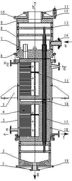
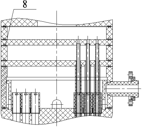
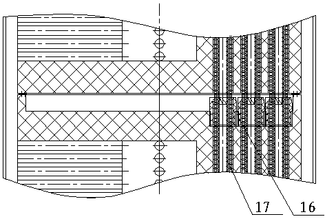
[0026] refer to Figure 1-7 , the falling film rectifier of the present invention comprises a cylinder 3, the lower end of the cylinder 3 is fixedly connected with the lower cover plate 19, the lower cover plate 19 is provided with a lower separator 2, and a lower connecting pipe is fixedly connected in the lower separator 2 1. A number of falling film graphite blocks 4 are accumulated sequentially in the cylinder body 3. A gas-liquid distribution plate 6 is placed on the first falling film graphite block 4 from top to bottom. The gas-liquid distribution plate Above 6 is a gas-liquid mixing chamber 8, at least one distribution weir 7 fixedly connected to the gas-liquid distribution plate 6 communicates with the gas-liquid mixing chamber 8, and a demister 13 is arranged on the top of the gas-liquid mixing chamber 8, and the top of the gas-liquid mixing chamber...


PUM


Abstract

The invention relates to a high-efficiency falling film type rectifier. According to the high-efficiency falling film type rectifier, the lower end of a barrel body is fixedly connected with a lower cover board; a lower separator is placed on the lower cover board; a plurality of falling film type graphite blocks are accumulated and arranged in the barrel body sequentially; a gas liquid mixing chamber is arranged above a gas liquid distribution disc; at least one distribution weir fixedly connected with the gas liquid distribution disc is communicated with the gas liquid mixing chamber; the top end of the gas liquid mixing chamber is fixedly connected with an upper cover board through a graphite cover board; a graphite connecting pipe is fixedly connected to the inside of the upper cover board; a mixed liquid material inlet is formed on the gas liquid mixing chamber; a steam inlet is formed on the upper part of the barrel body; a steam outlet is formed on the lower part of the barrel body; a purified material outlet is formed at the lower end of a lower connecting pipe; and a separated gas outlet is formed at the upper end of the graphite connecting pipe. The high-efficiency falling film type rectifier is characterized in that: at least one rectification weir is arranged on one falling film type graphite block on the middle section of the falling film type graphite blocks accumulated and arranged sequentially; and pipe hole type graphite regular fillers are arranged in vertical holes of the falling film type graphite blocks. The high-efficiency falling film type rectifier has the advantages of reasonable structure, good separation effect, high product purity and the like.

Description

technical field [0001] The invention relates to a device for separating alcohol and hydrogen chloride in triethyl phosphate, which is a falling film rectifier. Background technique [0002] The dealcoholization and deacidification device in existing triethyl phosphate, conventional equipment adopts glass-lined reactor, graphite condenser, vacuum unit to complete dealcoholization and deacidification process, and it is different according to the boiling point of triethyl phosphate, ethanol and hydrogen chloride , heating the material in the reaction kettle, the alcohol is heated up and gasified, and hydrogen chloride is released at the same time, and enters the condenser to condense. The disadvantages are that the device has small capacity, high energy consumption, long time and high cost, and the material is in the high-temperature gasification zone for a long time. , The leaked gas is flammable and explosive, and the acid-containing gas stays in the high-temperature area for...

Claims


Application Information

Patent Timeline
Patent Type & Authority Patents(China)
IPC IPC(8): B01D1/22B01D1/26B01D3/14C01B7/07C07C29/80C07C31/08
Inventor 陈勇金小龙宁永林范琳琳宁晓初
Owner JILIN SHUANGNING TECH
Why Eureka
Try Eureka