
Eureka
For R&D, Eureka makes reading and utilizing patents & technical documents easy.
Eureka AIR
Designed for self-driven R&D workflows. Generate viable solutions, solve complex R&D challenges, empower your innovation with AI.

Eureka Materials
Designed for material experts only. Revolutionize your material R&D, from search, analyze, to developing new materials.

TechResearch
Generate reliable direction feasibility study reports for your R&D in just a few steps.

TechSeek
Discover and master advanced knowledge NOW. Basics, ideas, possibilities, all at once.

TechMind
As an expert in R&D Theories, TechMind can generates customized viable solutions instantly.

TechRisk
Analyze your overall solution with one click, know your potential R&D risks in advance.

TechMonitor
Get weekly tech updates, stay abreast of the latest tech innovations and key insights.
Repairing compressor blades by cold compacting
A technology of compressor blades and blades, which is applied to the supporting elements of blades, mechanical equipment, engine manufacturing, etc., can solve problems such as the reduction of blade strength characteristics
- Summary
- Abstract
- Description
- Claims
- Application Information
AI Technical Summary
Problems solved by technology
Method used
Image

Examples
Embodiment Construction
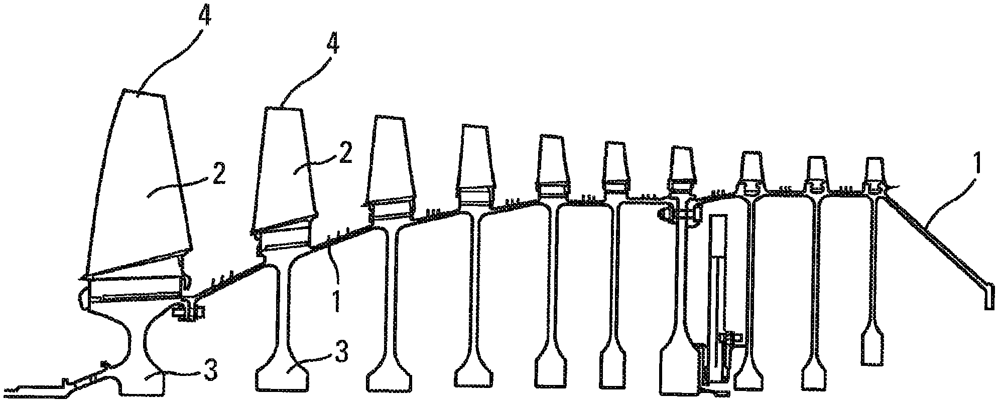
[0021] Referring to FIG. 1 , FIG. 1 shows a cross-section of a rotor 1 of a turbomachine compressor, including blades 2 mounted on the rotor 1 and a compressor disk 3 facing the blades 2 inside the rotor 1 . Each blade 2 has a root secured to the rotor 1 using techniques known to those skilled in the art, and the blades extend as far as the tip, or tip 4, to which the repair method that forms the subject of the present invention is directed.
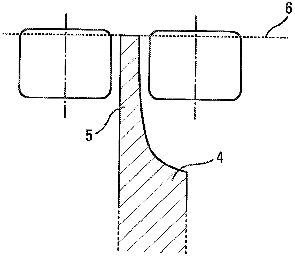
[0022] Referring to Figure 2, which is a radial cross-section of a blade tip, the shape of the blade tip is a sharp edge 4, the thickness of which is determined by the expected mechanical strength characteristics, and its radial extension has a thinner portion 5, which is referred to by those skilled in the art as The grooved tip is used to form a seal against the casing surrounding the compressor. This thinning of the groove tip is such that it inadvertently penetrates into the abradable material to which the casing is incorporated, so ...
PUM
| Property | Measurement | Unit |
|---|---|---|
| Height | aaaaa | aaaaa |
Abstract
Description
Claims
Application Information
 - R&D Engineer
- R&D Manager
- IP Professional
- Industry Leading Data Capabilities
- Powerful AI technology
- Patent DNA Extraction
Browse by: Latest US Patents, China's latest patents, Technical Efficacy Thesaurus, Application Domain, Technology Topic, Popular Technical Reports.
© 2024 PatSnap. All rights reserved.Legal|Privacy policy|Modern Slavery Act Transparency Statement|Sitemap|About US| Contact US: help@patsnap.com