Improved screw head

一种螺钉头、螺钉的技术,应用在螺钉、拉伸载荷作所特别改进的连接件、螺纹紧固件等方向,能够解决削弱系统、移植物和/或基牙厚度的等量减少、总尺寸不能改变等问题,达到减少摩擦的效果

Active Publication Date: 2012-07-11
STRAUMANN HLDG AG
View PDF12 Cites 0 Cited by
  • Summary
  • Abstract
  • Description
  • Claims
  • Application Information

AI Technical Summary

Problems solved by technology

However, space is limited in dental implant systems because the implant must fit within the available space within the jaw while removing as little bone as possible to limit trauma at the implant site
Therefore, the overall dimensions of the graft system cannot be changed, and any increase in screw diameter will result in an equivalent reduction in graft and / or abutment thickness
Such a modification would easily cripple the system in another area

Method used


Image

  • Improved screw head
  • Improved screw head
  • Improved screw head

Examples


Embodiment Construction

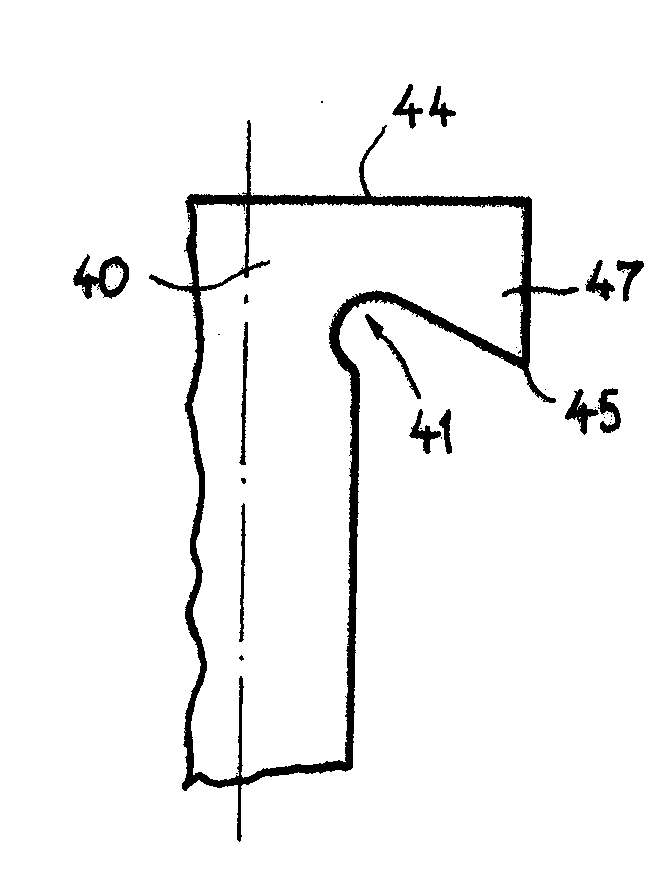
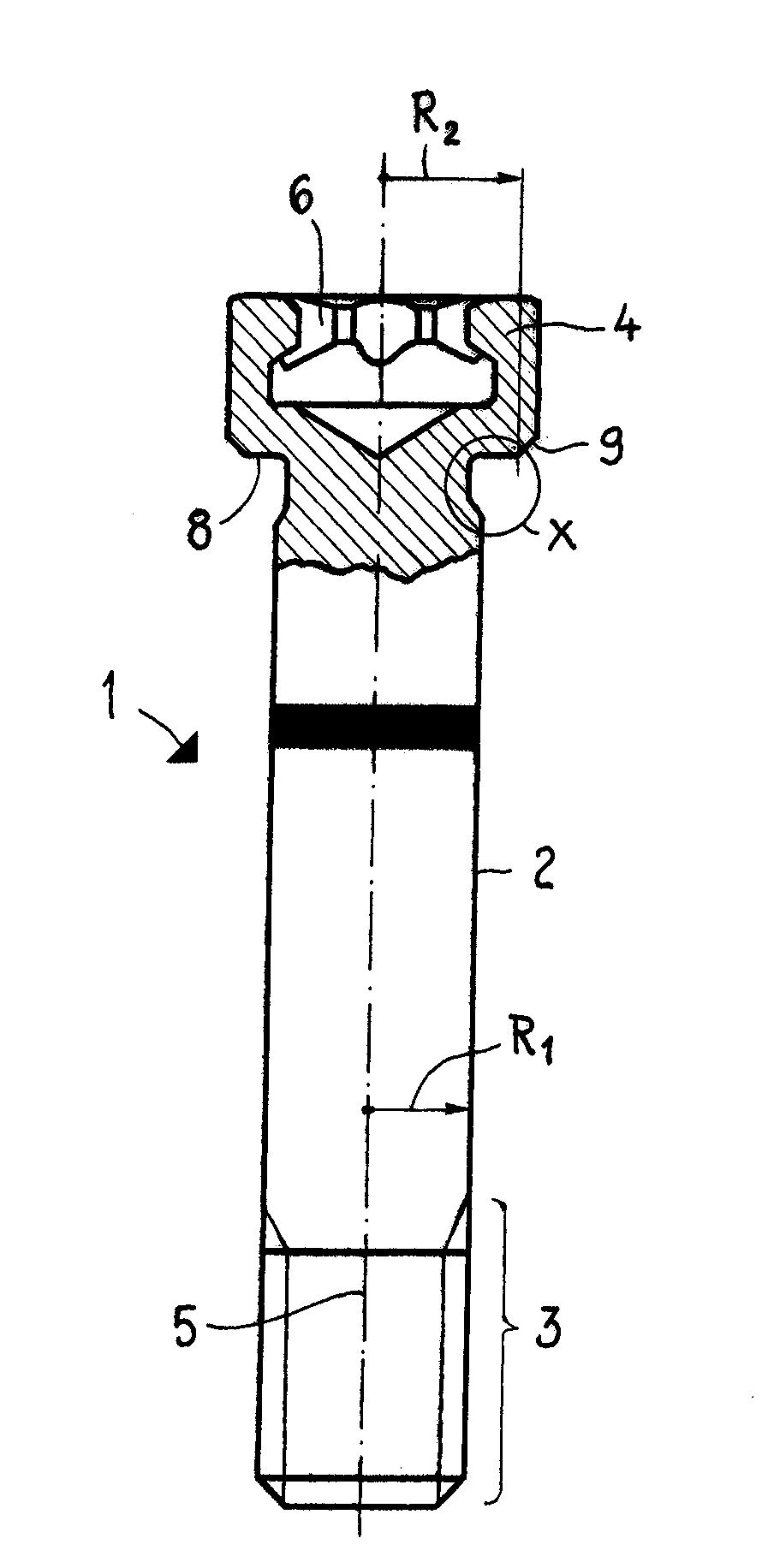
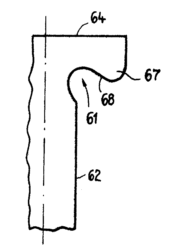
[0077] Figure 1A and B show a base screw 1 according to a prior art system. It comprises a screw shaft 2 extending along a longitudinal axis 5 . At its distal end, the shaft 2 includes a threaded portion 3, the size and pitch of which are selected to engage the internally threaded hole of the implant. At its opposite end, the shaft 2 is connected to the screw head 4 . The head 4 contains in its coronal end a hollow 6 shaped to allow the insertion of a driving tool such as a screwdriver. The hollow 6 has a non-circular symmetrical profile enabling torque to be transmitted from the driving tool to the screw 1 .

[0078] The maximum radius R of the bottom or top of the head 4 2 Greater than the maximum radius R of axis 2 1 . This results in an annular contact surface formed by the underside 8 of the screw head 4 . Since the abutment or other member to which the screw engages must include a screw channel dimensioned to allow passage of the screw shaft 2, the maximum possibl...


PUM


Abstract

A fastening system according to the present invention comprises a screw component (10) and a seating component (20). The screw component comprises a shaft (12) extending along a longitudinal axis (5) and having a maximum radius R 1 , said shaft comprising a threaded section (13), said screw component further comprising, at one end of the screw shaft, a head (14), the head comprising a bottom end (15) having a larger maximum radius R 2 than the screw shaft such that an exposed underside (18) of the screw head extends radially beyond the maximum radius of the screw shaft. The seating component comprises a screw channel (21) comprising a planar screw seat (22) having a minimum radius R 3 which is equal to or greater than R 1. The bottom end of the screw head comprises an annular contact surface for abutment against said screw seat, the contact surface being formed by the distal end of at least one downwardly extending protrusion (17) on the underside of the screw head, wherein the annular contact surface has a minimum radius greater than the minimum radius of the screw seat.

Description

technical field [0001] The present invention relates to screws, in particular those used in the field of dental implants for attaching secondary components, such as abutments, to dental implants. Background technique [0002] Dental implants are used to replace a single tooth or to anchor more complex structures that typically replace several or even all teeth. [0003] Grafts are usually constructed in two parts, in which case the graft consists of an anchoring part and a separate abutment, the anchoring part usually being called the graft in isolation. The anchoring element is either fully embedded in the bone, that is to say, up to the level of the alveolar ridge, or protrudes a few millimeters from the alveolar ridge into the soft tissue. The abutment is mounted on the anchor member and extends into the oral cavity to form support for the denture or denture. [0004] During the service life of the prosthesis, which can exceed 20 years, the graft system will be subjecte...

Claims


Application Information

Patent Timeline
Patent Type & Authority Applications(China)
IPC IPC(8): A61C8/00
CPCF16B35/06A61C8/0068F16B31/00A61C8/005A61C8/0059A61C8/0069A61C8/0074
Inventor S.库瓦西尔
Owner STRAUMANN HLDG AG
Why Eureka
Try Eureka