

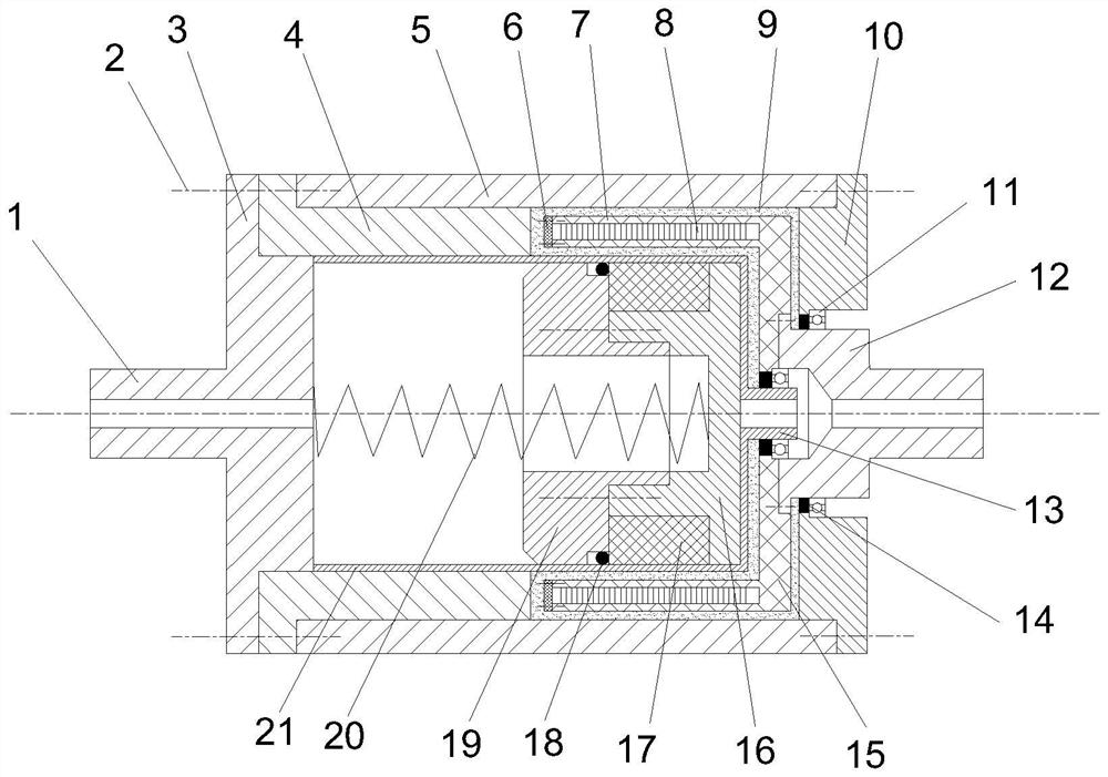
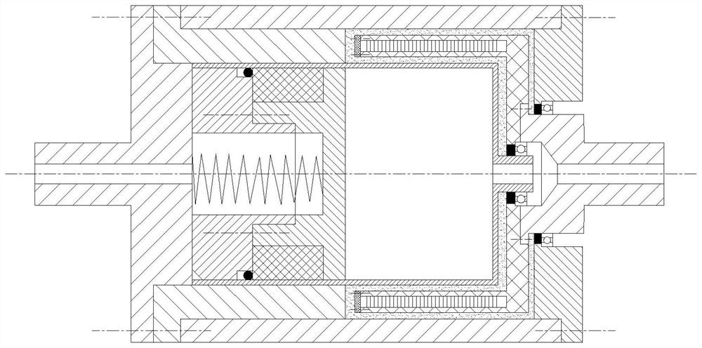
Double-shear magneto-rheological clutch under permanent magnet excitation
A magneto-rheological and double-shearing technology, which is applied to fluid clutches, clutches, mechanical equipment, etc., can solve the problems of increasing the size of the oil seal, reducing the utilization rate of the magnetic field, and failing to realize automatic fail-safe, etc., to increase the maximum torque and simple structure Effect
- Summary
- Abstract
- Description
- Claims
- Application Information
AI Technical Summary
Problems solved by technology
Method used
Image

Examples
Embodiment Construction
[0025] The following will clearly and completely describe the technical solutions in the embodiments of the present invention with reference to the accompanying drawings in the embodiments of the present invention. Obviously, the described embodiments are only some, not all, embodiments of the present invention. Based on the embodiments of the present invention, all other embodiments obtained by persons of ordinary skill in the art without making creative efforts belong to the protection scope of the present invention.
[0026] The purpose of the present invention is to provide a double-shear magneto-rheological clutch under permanent magnet excitation to solve the problems in the above-mentioned prior art. Magneto-rheological glue is used as the force transmission medium, and permanent magnets are used as the excitation source to achieve torque. The control has automatic fail-safe function, and has no magnetic field excitation energy consumption, and has the characteristics of...
PUM
 Abstract
Description
Claims
Application Information