Switched reluctance motor for electric vehicle

A technology of switched reluctance motors and electric vehicles, applied in electric vehicles, motors, electrical components, etc., can solve the requirements of permanent magnet ambient temperature and mechanical stress, which affect the maximum operating efficiency and maximum torque of the motor, and cannot produce the maximum torque motor Operational efficiency and other issues, to achieve the effect of low cost, low loss, stable and reliable quality

Inactive Publication Date: 2015-02-11
唐志新
View PDF0 Cites 0 Cited by
  • Summary
  • Abstract
  • Description
  • Claims
  • Application Information

AI Technical Summary

Problems solved by technology

However, permanent magnets have very strict requirements on the ambient temperature and mechanical stress of the application. At the same time, due to the increase in the price of rare earth materials in recent years, their cost has also increased accordingly.
The stator and rotor cores of existing reluctance motors generally adopt a double-salient pole cogging structure, such as figure 1 As shown, the internal teeth 111 of the stator are regular rectangular equidistantly arranged along the circumferential direction of the inner wall of the stator, and the internal teeth of the stator have insufficient torque when the motor is running, and cannot generate the maximum torque to improve the operating efficiency of the motor; figure 2 As shown, the outer teeth 112 of the rotor of the existing reluctance motor are also equidistantly arranged along the circumferential direction. However, the surface connected between the two outer teeth of the existing rotor is a plane, which affects the maximum operating efficiency and maximum torque of the motor. At the same time, the noise generated by friction during the operation of the motor cannot be solved well.

Method used


Image

  • Switched reluctance motor for electric vehicle
  • Switched reluctance motor for electric vehicle
  • Switched reluctance motor for electric vehicle

Examples


Embodiment Construction

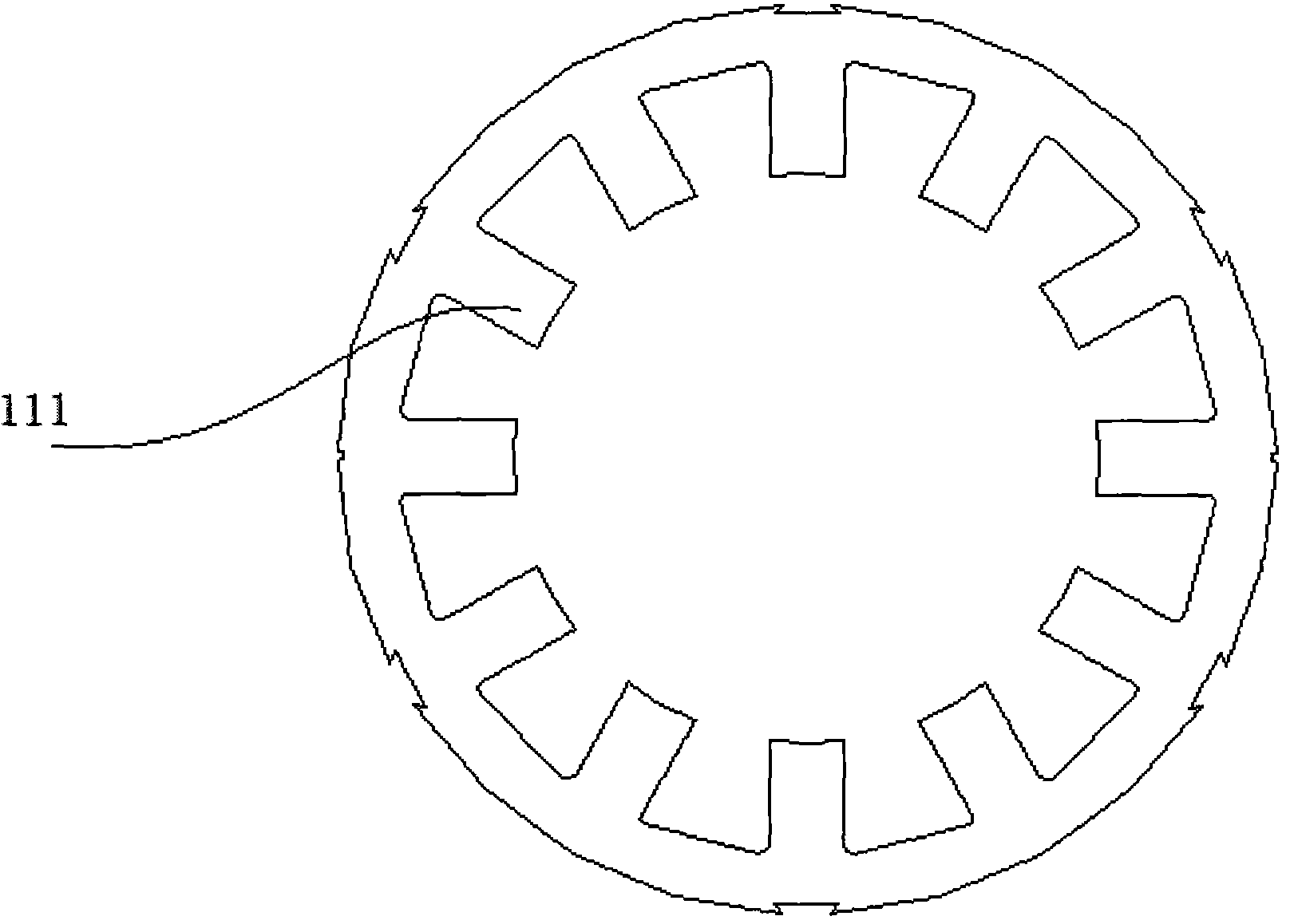
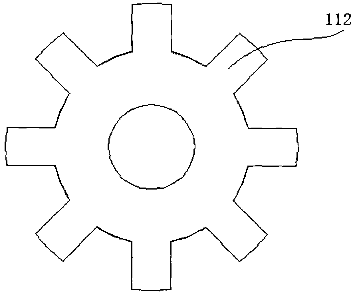
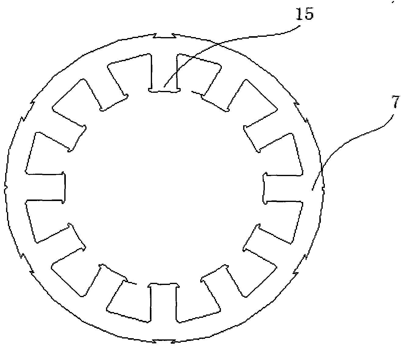
[0021] A switched reluctance motor for an electric vehicle provided by the present invention has a higher operating efficiency than a traditional series-excited motor and a brushless DC motor by setting a mutually fitted rotor-stator structure, and its loss is lower than that of an existing motor, and the cost is the lowest. The amount of enameled wire used in the coil is reduced by about 1 / 3 to 1 / 2 compared with the series excitation motor, and the adjustability is also higher than the traditional series excitation and brushless motor. At the same time, the reluctance motor of the present invention can run continuously for a long time, and the quality is stable and reliable .

[0022] The switched reluctance motor for electric vehicles provided by the embodiments of the present invention will be described in detail below with reference to the accompanying drawings.

[0023] Such as figure 1 , 2 , 3, 4, 5, and 6, a switched reluctance motor for an electric vehicle provided i...


PUM


Abstract

The present invention discloses a switched reluctance motor for an electric vehicle. The switched reluctance motor comprises a gear box cover, a gear baffle plate, a center gear, a front cover, a rotor, a motor shell, a stator, a back cover, a Hall sensor, a blade cover, a fan and a fan cover which are orderly arranged from front to back. The switched reluctance motor is characterized in that the top cross section of inner teeth is wider than that of a column body, and the connection surface of each two tooth roots of the outer teeth of the stator is in the shape of an inward taper. According to the motor, through arranging rotor and stator structures which are mutually embedded, the operation efficiency is higher than that of a traditional series excited motor and a brushless DC motor, the loss is lower than that of an existing motor, the cost is lowest, the enamelled wire dosage of a coil is reduced for 1 / 3 to 1 / 2 compared with that of the series excited motor, and the adjustability is higher than that of the traditional series excited motor and brushless DC motor. The switched reluctance motor has the advantages of long-term continuous operation and stable and reliable quality.

Description

technical field [0001] The invention relates to the technical field of driving motors for electric vehicles, in particular to a switched reluctance motor for electric vehicles. Background technique [0002] With the continuous development of society, electric vehicles have gradually become the main means of transportation in people's daily life. At the same time, the driving motor technology in electric vehicles is also constantly updated. Traditional electric vehicles mostly use series-excited motors. With the continuous development of electric vehicle technology, a new type of brushless DC motor has appeared on the market. After comparing the two motors, the operating efficiency of the series-excited motor is lower than that of the brushless DC motor. 10%, at the same time, the loss of the series excitation motor is higher than that of the brushless DC motor, and the cost comparison is due to the large amount of rare earth required by the brushless DC motor, and the cost o...

Claims


Application Information

Patent Timeline
Patent Type & Authority Applications(China)
IPC IPC(8): H02K29/08
CPCY02T10/64
Inventor 顾浩良
Owner 唐志新
Why Eureka
Try Eureka