Multiple component dispensing cartridge, mixing nozzle and method for reducing contact between fluids

A technology for mixing nozzles and fluids, used in chemical instruments and methods, mixers, fluid mixers, etc., and can solve problems such as difficulty and blockage

Active Publication Date: 2012-07-11
NORDSON CORP
View PDF7 Cites 16 Cited by
  • Summary
  • Abstract
  • Description
  • Claims
  • Application Information

AI Technical Summary

Problems solved by technology

This presents difficulties such as when reusing a cartridge with an attached mixing nozzle or when removing and later replacing a used mixing n

Method used


Image

  • Multiple component dispensing cartridge, mixing nozzle and method for reducing contact between fluids
  • Multiple component dispensing cartridge, mixing nozzle and method for reducing contact between fluids
  • Multiple component dispensing cartridge, mixing nozzle and method for reducing contact between fluids

Examples


Embodiment Construction

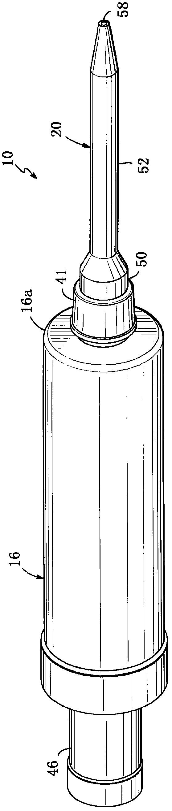
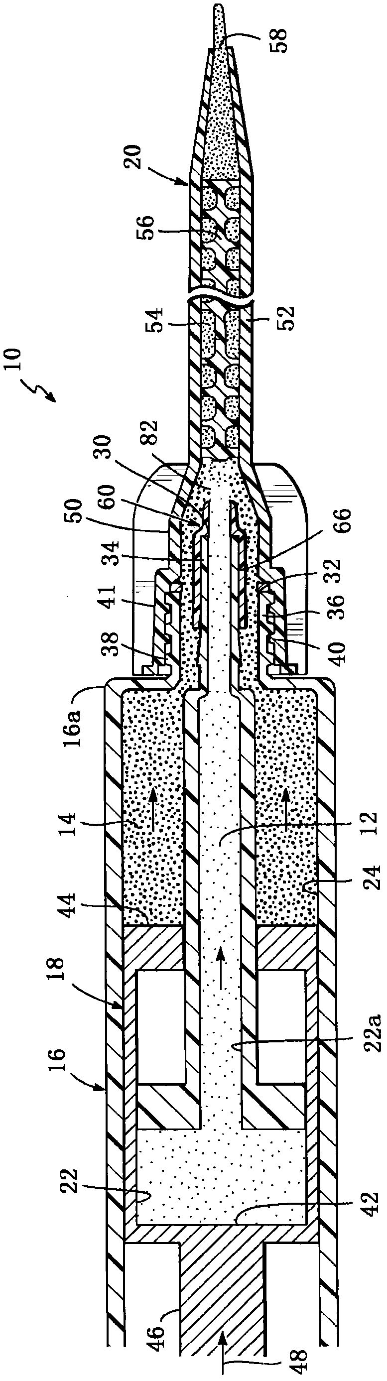
[0024] First refer to figure 1 and figure 2 , shows a fluid cartridge 10 for mixing and dispensing a first fluid 12 and a second fluid 14, and the fluid cartridge 10 generally includes a housing 16, a piston unit 18 mounted in the housing 16, and a piston unit 18 coupled to the housing The mixing nozzle 20 at the distal end 16a of the body 16. It should be understood that the housing 16 and piston unit 18 may take many different designs and that the designs shown here are for illustrative purposes only. For more details regarding the operation of the piston unit 18, reference may be made to US Patent No. 7,748,567, the disclosure of which is incorporated herein by reference.

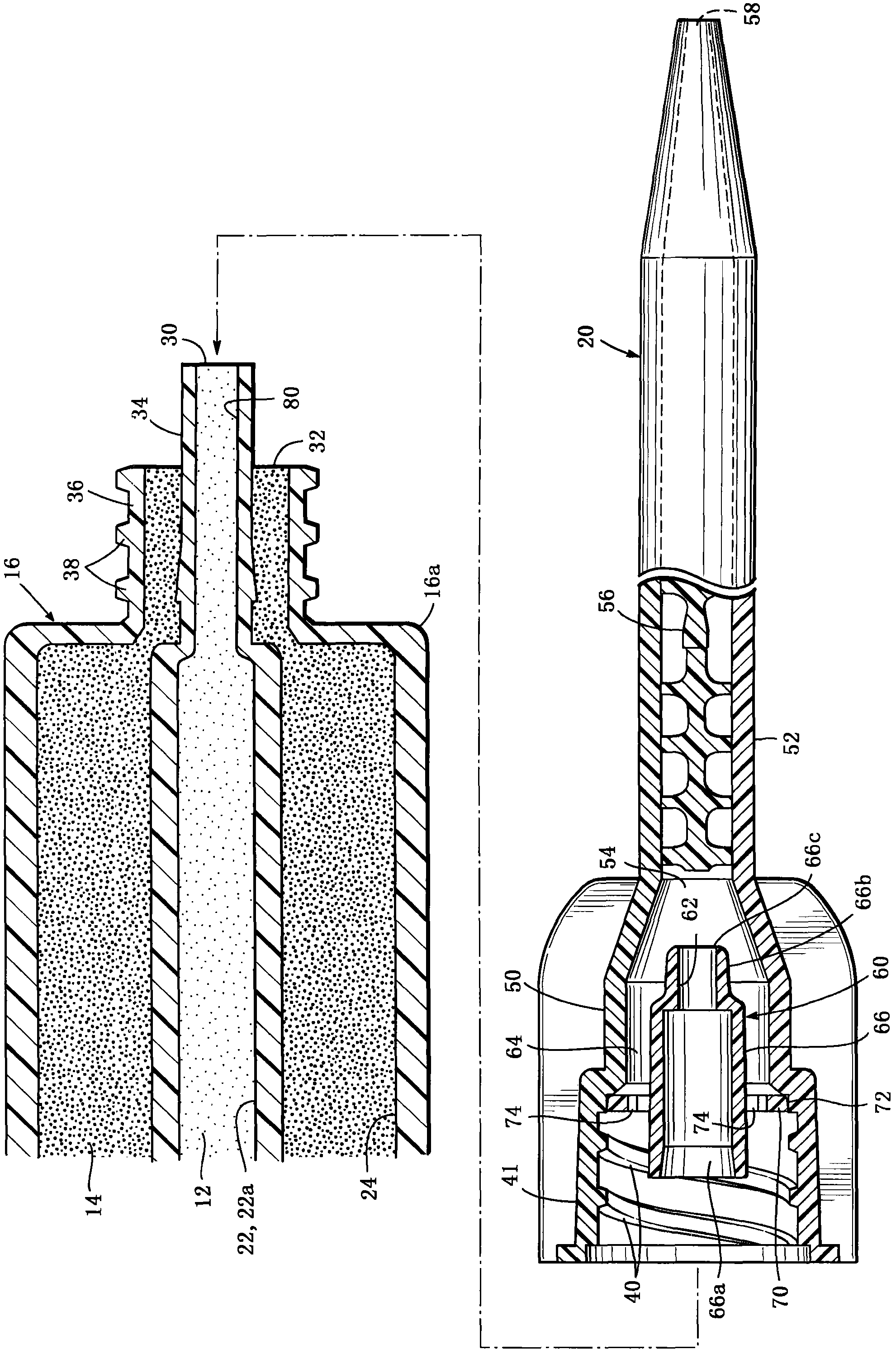
[0025] Generally, the housing 16 includes first and second fluid chambers 22, 24 to hold the first and second fluids 12, 14, respectively. The second fluid chamber 24 is an annular chamber disposed in surrounding relationship with the front or distal portion 22a of the first chamber 22 . The piston ...


PUM


Abstract

The present invention relates to a multiple component dispensing cartridge, a mixing nozzle and a method for reducing contact between fluids. A fluid cartridge for mixing and dispensing first and second luids includes a housing, a piston unit mounted in the housing, and a mixing nozzle. The mixing nozzle includes a first portion releasably attachable to a distal end of the housing and a second portion located distal to the first portion. An internal fluid passage communicates between the first and second portions. A static mixing element is located in the second portion and a distal dispensing opening communicates with the static mixing element. A tubular fluid separator element is located in the first portion and defines first and second flow passages. The first flow passage is a central passage and the second flow passage is radially outside of the first flow passage. The fluid separator element maintains the flow of the first fluid separate from the flow of the second fluid in the first portion of the mixing nozzle.

Description

technical field [0001] The present invention generally relates to multi-fluid component mixing and dispensing cartridges of the type utilizing static mixing nozzles. Background technique [0002] There are various types of multi-component mixing and dispensing devices, including those in which the fluid chambers are in a side-by-side configuration, and those in which the fluid chambers are in a coaxial configuration. Such cartridges may typically be placed in a hand-held applicator or gun having one or more movable plungers. The plunger moves a piston associated with the fluid chamber to dispense and mix the two component fluids at the distal end of the cartridge. [0003] Fluid cartridges of this general type include respective first and second outlets at the distal end for dispensing the two fluids from the fluid chamber into the mixing nozzle. The mixing nozzle comprises internal static mixing elements which repeatedly combine the layers of the two liquids for mixing pu...

Claims


Application Information

Patent Timeline
IPC IPC(8): B05B7/04B05B7/08B05B11/02
CPCB01F15/0224B05C17/01B05C17/00559B01F15/0237B01F15/0087B01F5/0615B01F13/0023B05C17/00513B05C17/005B01F25/43141B01F33/50112B01F35/522B01F35/7162B01F35/7174B05B7/02B05B7/06
Inventor 马修·E·帕帕拉尔多
Owner NORDSON CORP
Why Eureka
Try Eureka