Check patentability & draft patents in minutes with Patsnap Eureka AI!

Injection device

A technology of injection device, syringe, applied in the direction of syringe, automatic injector, hypodermic injection equipment, etc.

Active Publication Date: 2012-07-18
CILAG GMBH INT
View PDF8 Cites 15 Cited by
  • Summary
  • Abstract
  • Description
  • Claims
  • Application Information

AI Technical Summary

Problems solved by technology

this can have adverse consequences

Method used


Image

  • Injection device
  • Injection device
  • Injection device

Examples


Embodiment Construction

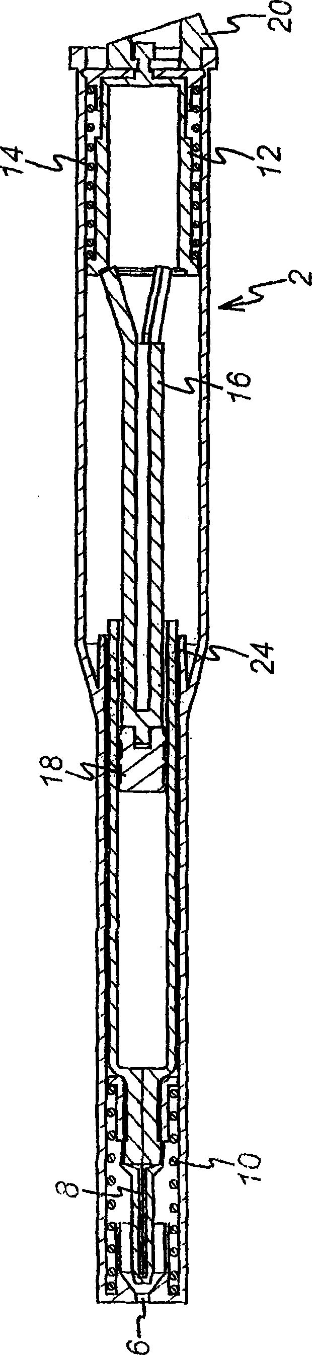
[0057] The present invention may be contained within any suitable housing, such as that shown in FIG. The opposite end has a release mechanism 20 for releasing the spring 14 which deploys and empties the contained syringe.

[0058] figure 2 The key building blocks for the preferred embodiment of the preferred housing are shown schematically.

[0059] The drive spring 30 engages a first engagement element 32 which itself provides power to a second engagement element 34 . The drive spring 30 thus acts here as a movement-generating means for the injection device. Alternatively, motion generating components such as pneumatic pistons operated by compressed gas tanks or actuators of electromagnetic coils in electric devices may be used. The second engagement element 34 is arranged to engage the dispensing piston 18 of the syringe 4 in the device. Thus, when the engagement elements 32, 34 are released by a suitable release mechanism, the drive spring 30 drives the first engageme...


PUM


Abstract

An injection device including a housing for containing a syringe (4) having a dispensing piston (18) to expel the contents of the syringe through the needle (8), a resilient member (40) for biassing the syringe and the needle inwardly off the housing, a first coupling element (32) moveable towards said one end so as to move the needle of the syringe out of the opening and to move the dispensing piston of the syringe towards the end of the surface, a mechanism operable to release the syringe such that the needle moves inwardly off the housing,; a drive coupling for extending from said first coupling element to the dispensing piston of the syringe so as to transfer movement of said first coupling element to the dispensing piston wherein the mechanism is triggered to release the syringe and includes components to delay release of the syringe until a predetermined period after being triggered such that it can be ensured that the dispensing piston reaches the end surface before the syringe is released.

Description

technical field [0001] The present invention relates to an injection device, and more particularly, to an injection device that automatically retracts the needle of the syringe after dispensing the contents of the syringe. Background technique [0002] There are devices that are spring loaded to automatically extend the needle of the syringe from the device, dispense the contents of the syringe and then automatically retract the needle. Such a device is described in WO 95 / 35126. [0003] As shown in FIG. 1 of the accompanying drawings, the device comprises a housing 2 housing a syringe 4 . The housing 2 comprises an opening 6 through which the needle 8 of the syringe 4 can protrude. Return spring 10 biases syringe 4 away from opening 6 . The device also comprises a drive element 12 biased by a spring 14 to drive an adapter 16 and thereby move a dispensing piston 18 of the syringe 4 . In use, the release mechanism 20 releases the drive element 12 so that the syringe 4 is ...

Claims


Application Information

Patent Timeline
Patent Type & Authority Applications(China)
IPC IPC(8): A61M5/50A61M5/20A61M5/315A61M5/32
CPCA61M5/2033A61M5/3287A61M2005/3143A61M2005/31516A61M5/326A61M2005/206A61M5/16804A61M5/20A61M5/3234A61M5/32A61M5/168
Inventor 奈杰尔·戴维·哈里森马修·詹姆斯·布雷迪格雷戈里·伯曼戴维·马克斯韦尔·约翰斯顿罗斯玛丽·路易丝·哈伯肖
Owner CILAG GMBH INT
Features
  • R&D
  • Intellectual Property
  • Life Sciences
  • Materials
  • Tech Scout
  • Unparalleled Data Quality
  • Higher Quality Content
  • 60% Fewer Hallucinations
Learn More