
Front safety girder and rear safety girder capable of realizing rigidity and flexibility combined efficient buffering energy absorption

A rigid-flexible, automotive technology, used in bumpers and other directions

Inactive Publication Date: 2012-07-18
黄玉兰 +1
View PDF7 Cites 5 Cited by
  • Summary
  • Abstract
  • Description
  • Claims
  • Application Information

AI Technical Summary

Problems solved by technology

[0010] At present, all kinds of automobiles at home and abroad and all kinds of automobile passive safety devices that have been or are being developed can meet the above five design principles at the same time, and no reports or patents have been published (published) yet.

Method used


Image

  • Front safety girder and rear safety girder capable of realizing rigidity and flexibility combined efficient buffering energy absorption
  • Front safety girder and rear safety girder capable of realizing rigidity and flexibility combined efficient buffering energy absorption
  • Front safety girder and rear safety girder capable of realizing rigidity and flexibility combined efficient buffering energy absorption

Examples


Embodiment Construction

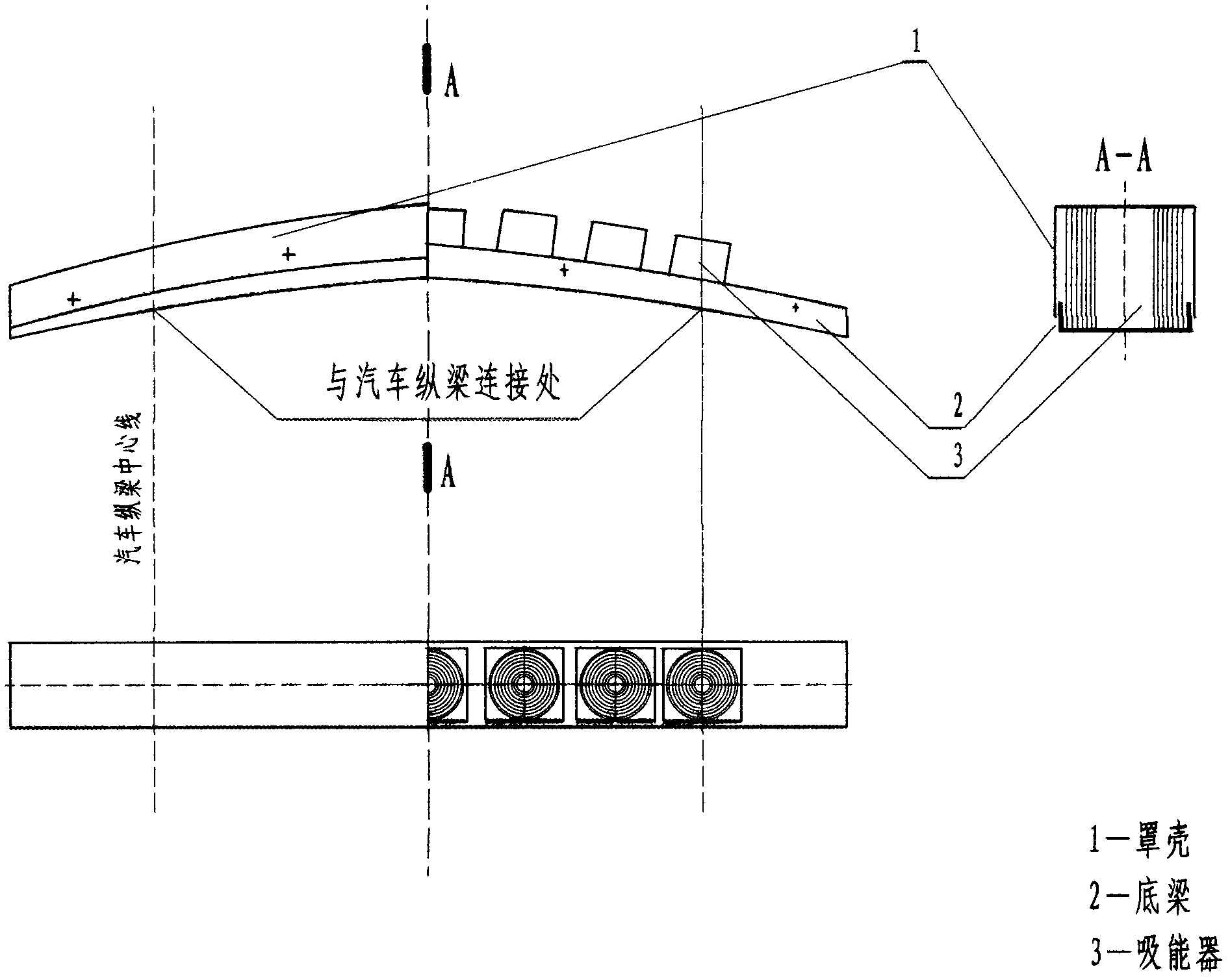
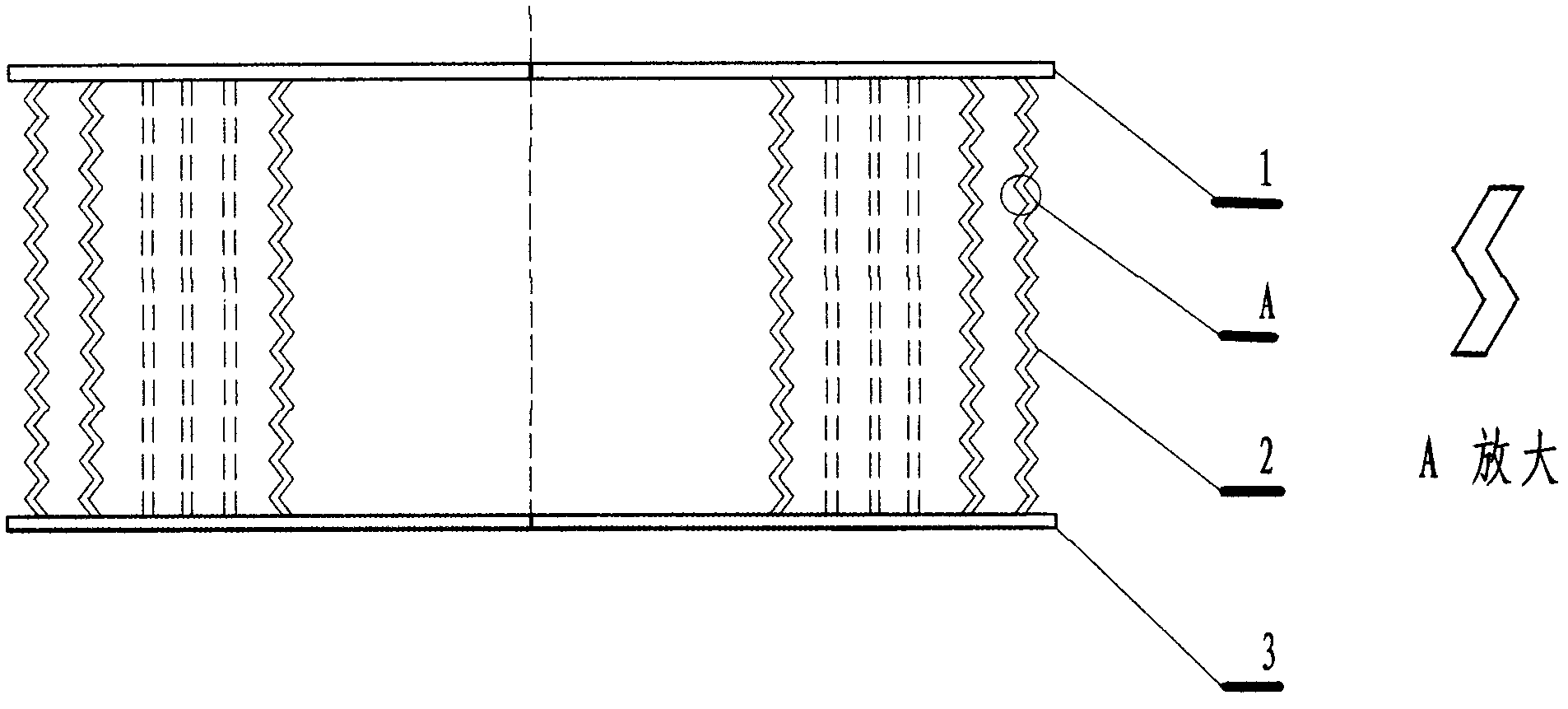
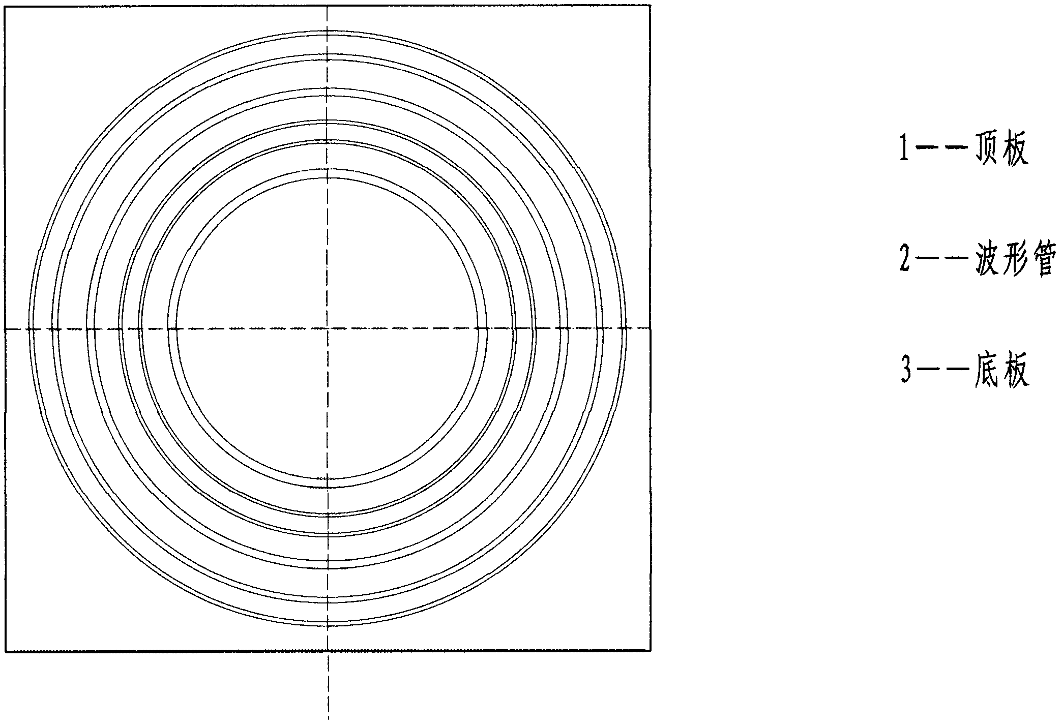
[0055] see Figure 1-3 According to the embodiment of the present invention, in the front safety beam and the rear safety beam of the automobile, according to the requirements and positions calculated by the design, the figure 2 The high-efficiency energy absorbers are welded and installed at the bottom of the front and rear sills. see figure 1 In the A-A sectional view, the centerline of the main energy absorber 3 should be installed facing the centerline of the front and rear longitudinal beams of the car, and the auxiliary energy absorbers should be installed in front of the centerline of the front and rear safety beams and evenly distributed on the left and right.

[0056] figure 1 The casings 1 of the front and rear safety beams in the middle A-A section should be installed on the bottom beam and the main and auxiliary energy absorbers, and cover the bottom beams and energy absorbers, but the casing and the bottom beam are flexibly connected, that is, the bottom beam ...


PUM


Abstract

The invention relates to a new-generation automobile passive safety device which replaces a front anti-collision girder and a rear anti-collision girder by a front safety girder and a rear safety girder capable of realizing rigidity and flexibility combined efficient buffering energy absorption on the basis of calculating energy absorption theoretically under the condition that the structure, the shape, the appearance and the functions of an automobile body are not changed. The safety girders are arranged on the two end surfaces of a front longitudinal girder and a rear longitudinal girder of an automobile with the adoption of the positions and cavities that are used for installing the front anti-collision girder and the rear anti-collision girder of the automobile; each safety girder consists of an energy absorber housing, a plurality of main efficient buffer energy absorbers, a plurality of auxiliary buffer efficient buffer energy absorbers and a bottom girder; the bottom girders are rigid stressed parts; the housings and the energy absorbers are flexible energy absorption parts; and the safety girders have the structure characteristic of combination of rigidity and flexibility, the adverse effect on the original anti-collision girders is eliminated in the high-speed and medium-speed collision, the anti-impact capability of the automobile is improved obviously, and the personal safety of drivers and passengers can be protected to the maximum degree. Based on the verification of embodiments, compared with the prior art, the safety, the technicality, the economy and other aspects are all better than those of the original anti-collision girders, and the replacement of the anti-collision girders by the safety girders with obvious energy absorption effect necessarily becomes the direction of the development of the automobile safety technology.

Description

technical field [0001] The invention relates to automobile safety in the technical field of traffic safety, in particular to an energy-absorbing energy-absorbing device that combines rigidity and flexibility with high-efficiency energy absorption under the condition of keeping the structure, shape, appearance and function of the automobile body unchanged on the basis of theoretical calculation of energy absorption. A new generation of automotive passive safety devices that replace the front and rear anti-collision beams. Background technique [0002] At present, the most advanced vehicle active safety technology in the world is the intelligent automatic driving device. This active safety technology has achieved preliminary results at home and abroad, but it is still in the trial and trial stage. This active safety device includes a detection system, computer analysis and control, commands to the steering and braking system, and various alarms, etc. The entire device system i...

Claims


Application Information

Patent Timeline
IPC IPC(8): B60R19/18
Inventor 柳正清蔡桂元
Owner 黄玉兰
Learn More