Single-cable electric grab bucket

A technology of electric grab and single rope, which is applied in the direction of transportation and packaging, load hanging components, etc., can solve the problems of large occupied space, heavy grab bucket, and poor grasping of goods by the grab bucket, so as to reduce the occupied space Space, improved handling capacity, strong handling effect

Active Publication Date: 2014-03-05
苏州阿代尔信息科技有限公司
View PDF7 Cites 0 Cited by
  • Summary
  • Abstract
  • Description
  • Claims
  • Application Information

AI Technical Summary

Problems solved by technology

[0002] Grab buckets are important handling equipment for handling bulk cargo in large and small ports. Most of the grab buckets in existing ports are installed on cranes, cranes or door cranes. They generally include hoods, motors, reducers, and wire rollers inside the hoods. There is an upper bolster under the hood, an upper bolster pulley is set on the upper bolster, a lower bolster is set under the upper bolster, and a lower bolster pulley is set on the lower bolster, and one side of the two buckets is hung on the lower bolster. On the bolster, the other sides of the two buckets are flexibly connected to the hood through connecting rods, and the steel wire roller, the upper bolster pulley and the lower bolster pulley are flexibly connected by wire ropes. Since the upper bolster is in the horizontal direction It has an X-shaped structure, and the rotation angle of the upper bolster is relatively large, resulting in a large space occupied by the upper bolster and the pulleys of the upper bolster, which makes the hood of the grab bucket too large, and the weight of the grab bucket is heavy. The capacity is low. At the same time, because the existing control device for opening and closing the grab is located next to the wire rope, the shaking or jumping of the wire rope can cause the opening and closing control device of the grab to open and close abnormally, so that the opening and closing of the grab is not correct. Stable, causing the grab to grab the goods not firmly, easy to scatter the goods, affecting the handling work of the grab

Method used


Image

  • Single-cable electric grab bucket
  • Single-cable electric grab bucket
  • Single-cable electric grab bucket

Examples


Embodiment Construction

[0013] Below in conjunction with embodiment the present invention is described in further detail.

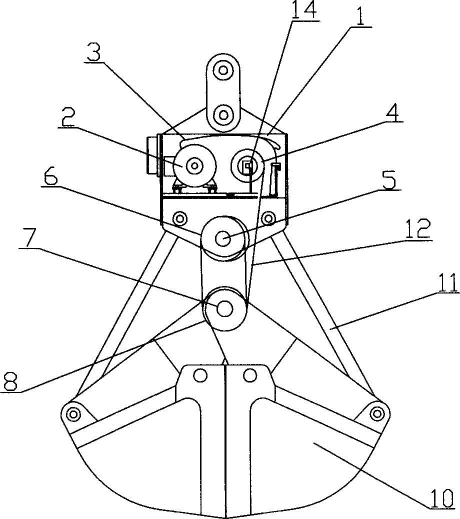
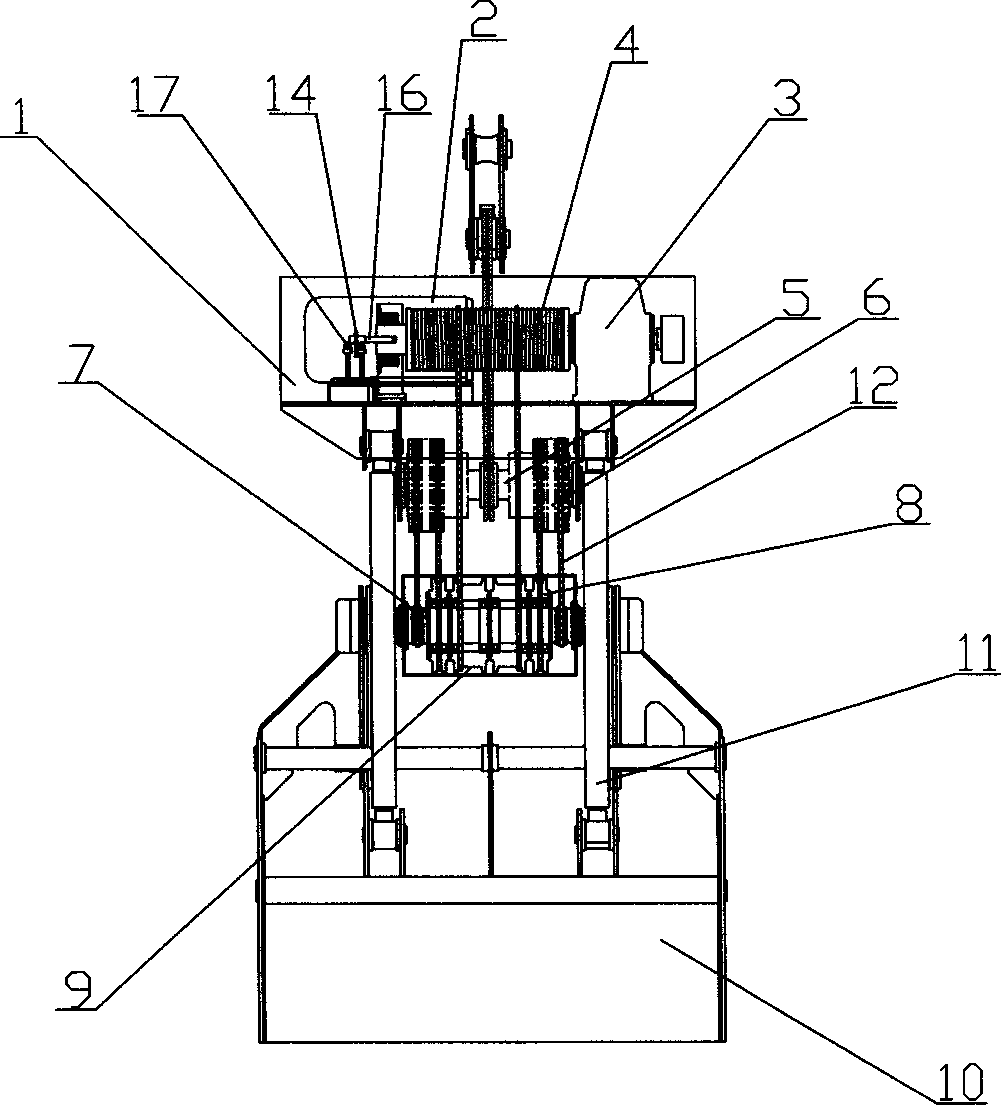
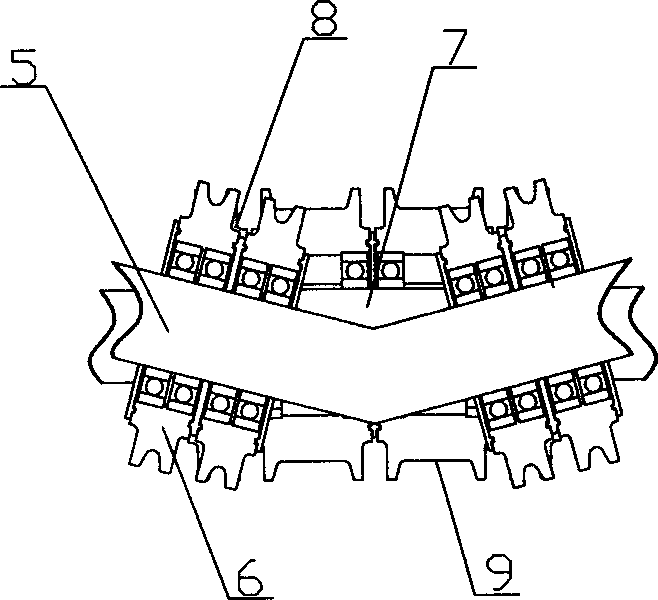
[0014] Depend on figure 1 , figure 2 with image 3 It can be seen that a single-cable electric grab according to the present invention includes a head cover 1, a motor 2, a reducer 3, a steel wire roller 4, an upper bolster, an upper bolster pulley, a lower bolster, a lower bolster pulley, Two bucket bodies 10, support rods 11, steel wire ropes 12 and grab opening and closing control devices; the motor 2, the reducer 3 and the steel wire roller 4 are arranged inside the hood 1, and the upper bolster 5 is arranged under the hood 1 , the upper bolster 5 is arranged in a figure-eight shape on the horizontal plane, and the upper bolster 5 is actually a folded whole shaft on the horizontal plane. Bearing beam pulley 6, lower bearing beam 7 is provided at the lower corresponding position of upper bearing beam 5, lower bearing beam 7 is a straight shaft, and lower bearing beam 7 is...


PUM


Abstract

The invention relates to a single-cable electric grab bucket comprising a hood, a motor, a reduction gear, a steel wire roller, an upper deck beam, upper deck beam pulleys, a lower deck beam, lower deck beam pulleys, two bucket bodies, brace rods, a steel wire and an opening and closing control device, wherein the upper deck beam is configured in a splayed shape in a horizontal plane, two upper deck beam pulleys with a plurality of sliding chutes are symmetrically sleeved on the upper deck beam, the lower deck beam is a straight shaft, two lower deck beam pulleys with a plurality of sliding chutes are symmetrically sleeved on the lower deck beam, the lower deck beam pulleys correspond to the upper deck beam pulleys with regard to the sliding chutes, and the sliding chutes at the two inner sides of the two lower deck beam pulleys are wide-edge sliding chutes with larger width. According to the single-cable electric grab bucket disclosed by the invention, because the traditional steel wire winding manner is changed, the space occupied by the upper deck beam and the upper deck beam pulleys is reduced, the box body of the hood is reduced greatly, the self weight of the grab bucket is reduced, and the actual transporting capacity of the grab bucket is increased.

Description

(1) Technical field: [0001] The invention relates to port handling equipment, in particular to a single-cable electric grab. (two) background technology: [0002] Grabs are important handling equipment for handling bulk cargo in large and small ports. Most of the grabs in existing ports are installed on cranes, cranes or door cranes. They generally include hoods, motors, reducers, and wire rollers inside the hoods. There is an upper bolster under the hood, an upper bolster pulley is set on the upper bolster, a lower bolster is set under the upper bolster, and a lower bolster pulley is set on the lower bolster, and one side of the two buckets is hung on the lower bolster. On the bolster, the other sides of the two buckets are flexibly connected to the head cover through connecting rods, and the steel wire roller, the upper bolster pulley and the lower bolster pulley are flexibly connected by wire ropes. Since the upper bolster is in the horizontal direction It has an X-shape...

Claims


Application Information

Patent Timeline
Patent Type & Authority Patents(China)
IPC IPC(8): B66C3/18B66C3/04
Inventor 陈礼勇陈礼卫陈礼所陈华
Owner 苏州阿代尔信息科技有限公司
Why Eureka
Try Eureka