Welding method for U-shaped ribs of orthotropic plate of bridge girder

A welding method and orthotropic bridge technology, which are applied in welding equipment, arc welding equipment, workpiece edge parts, etc., can solve the problem of reducing the amount of weld metal filling, increasing the size of the blunt edge of the groove, and reducing the amount of groove processing. and other problems, to achieve the effect of reducing the amount of weld metal filling, reducing the filling area, and reducing the amount of groove processing

Active Publication Date: 2012-07-25
CHINA RAILWAY BAOJI BRIDGE GRP
View PDF5 Cites 16 Cited by
  • Summary
  • Abstract
  • Description
  • Claims
  • Application Information

AI Technical Summary

Problems solved by technology

[0005] The design idea of ​​the present invention: argon-rich gas shielded welding, due to its own welding arc characteristics, it is easy to obtain the droplet transition form of the jet, the arc penetration is large, and it is easy to solve the problem of U-rib penetration; the use of solid welding wire rich in argon Slag and flux cored wire CO produced by gas shielded welding 2 The characteristics of the slag formed by shielded welding are different. The slag of solid wire argon-rich gas shielded welding floats upward during the solidification process of the molten pool, which fundamentally solves the problem of slag inclusion at the root of the weld; , so the size of the blunt edge of the groove can be increased, the amount of groove processing can be reduced, the amount of weld metal filling can be reduced, and the cost of welding materials can be saved; the adjustment of the surface tension of the molten pool can realize horizontal welding and the weld shape is beautiful, and Multi-head portal welding can be used at the same time to weld a bridge deck at one time, greatly improving production efficiency and reducing production costs; using solid welding wire will not generate a lot of smoke and dust like flux-cored welding wire, and it is a cleaner welding process

Method used


Image

  • Welding method for U-shaped ribs of orthotropic plate of bridge girder
  • Welding method for U-shaped ribs of orthotropic plate of bridge girder
  • Welding method for U-shaped ribs of orthotropic plate of bridge girder

Examples


Embodiment Construction

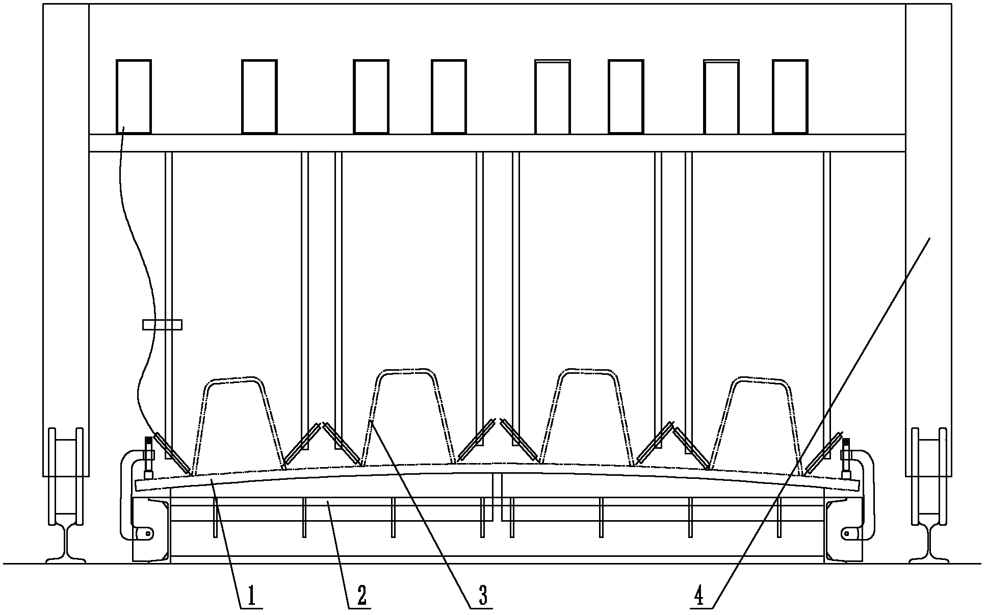
[0027] Attached below figure 1 , 3 , 4 describe the first embodiment of the present invention.

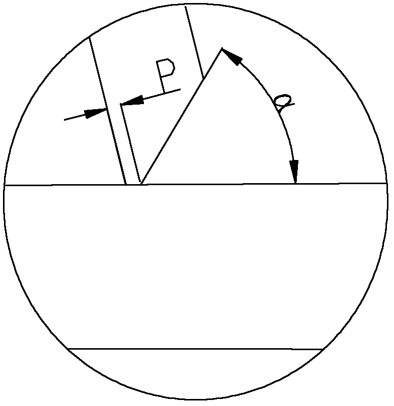
[0028] 1) Make a bevel on the outside of the 6mm U-shaped rib 3, the blunt side P is 1.5mm, and the bevel angle α is 50°;

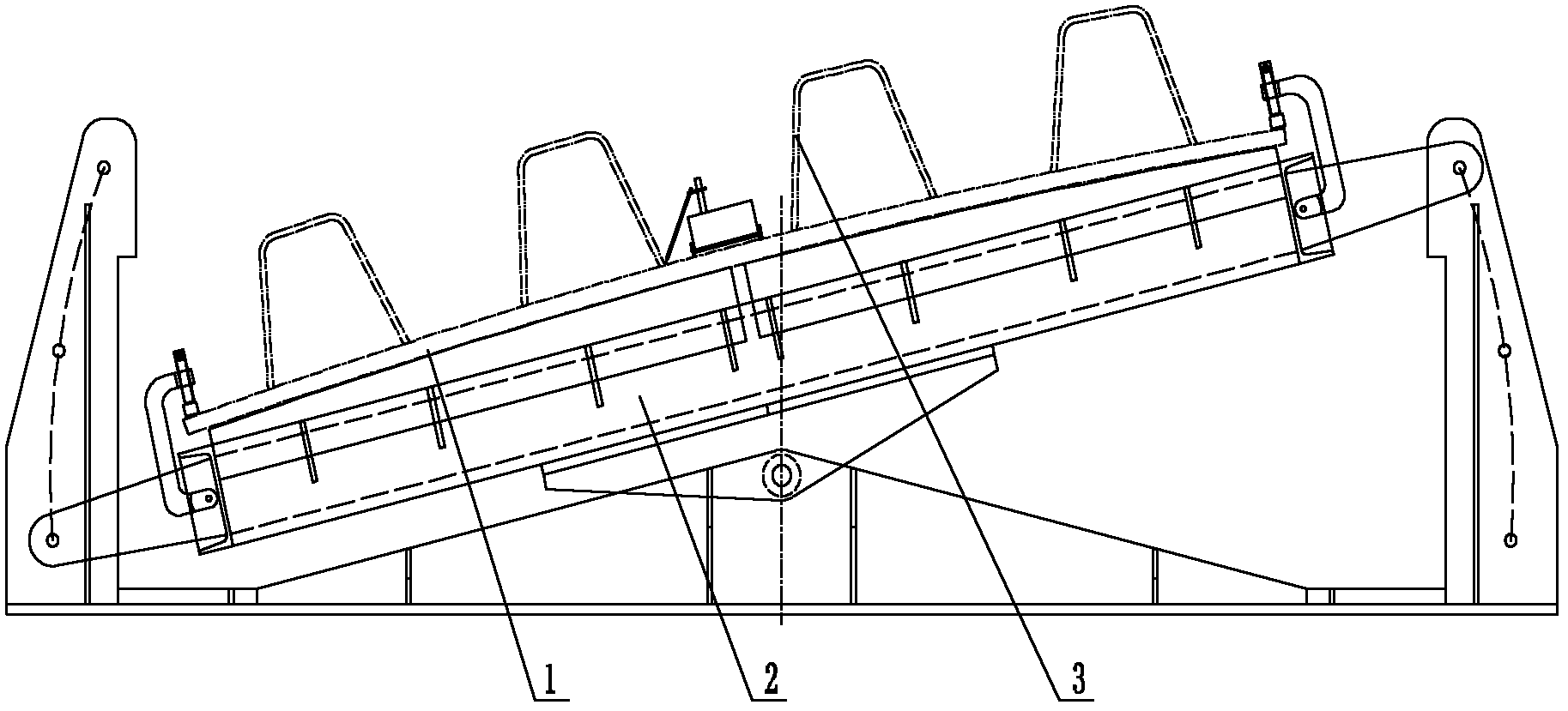
[0029] 2) Arrange the U-shaped ribs 3 longitudinally on the bridge deck 1 according to the designed position and position them by spot welding;

[0030] 3) Fix the bridge deck 1 with a yield strength of 345MPa to 390Mpa on the anti-deformation tire frame 2, and the anti-deformation angle is 0.4°;

[0031] 4) Set the horizontal multi-head door-type automatic welding machine 4 above the anti-deformation tire frame 2, so that the bridge deck 1 is located at the welding station of the horizontal multi-head door-type automatic welding machine 4, and then use the horizontal position welding method to weld the U-shaped The rib 3 is welded on the bridge deck 1 by one long piece. The welding adopts a solid welding wire argon-rich gas shielded welding process. The ...


PUM

PropertyMeasurementUnit
yield strengthaaaaaaaaaa
thicknessaaaaaaaaaa
yield strengthaaaaaaaaaa

Abstract

A welding method for U-shaped ribs of an orthotropic deck plate of a bridge girder comprises the following steps that: 1) bevels are formed at the outer sides of the U-shaped ribs, each truncated edge P is 1-3mm, and the angle alpha of each bevel is 45-55 degrees; 2) the U-shaped ribs are longitudinally arranged on the deck plate and are positioned on the deck plate; 3) the deck plate is fixed on a reversible deformation jig frame, and the reversible deformation angle is 0.3-0.45 degrees; and 4) the U-shaped ribs are wholly welded on the deck plate through a solid welding wire argon-riched shielded welding process. According to the welding method, the defects in the prior art can be overcome, and the welding method has the advantages that the safety and the reliability are good, the efficiency is high, the cost is low, etc.

Description

technical field [0001] The invention belongs to the technical field of bridge steel structure welding, and in particular relates to a method for welding U-shaped ribs of bridge orthotropic deck decks. Background technique [0002] The orthotropic slab deck is a bridge deck structure in which longitudinal U-shaped stiffeners, transverse stiffeners, and bridge decks are welded together to bear wheel loads. It is composed of bridge deck, U-shaped ribs and transverse ribs. The three are perpendicular to each other and work together. Compared with other bridge decks, it can not only bear the direct effect of vehicle wheel load, but also participate in the joint work of the main girder, so it has the advantages of light weight, steel saving and high bearing capacity in bridges all over the world, especially long-span bridges. has been widely applied. In the orthotropic slab bridge deck structure, the welds between the face plate and the longitudinal U-shaped ribs are dense, gene...

Claims


Application Information

Patent Timeline
Patent Type & Authority Applications(China)
IPC IPC(8): B23K9/16B23K33/00
Inventor 袁俊孙立雄张剑峰车平
Owner CHINA RAILWAY BAOJI BRIDGE GRP
Why Eureka
Try Eureka