


Quick Research
Generate reliable direction feasibility study reports for your R&D in just a few steps.

Technical Q&A
Discover and master advanced knowledge NOW. Basics, ideas, possibilities, all at once.

Find Solutions
As an expert in R&D theories, this can generate solutions to your technical problems instantly.

Evaluate Feasibility
Analyze your overall solution with one click, know your potential R&D risks in advance.

Monitor Landscape
Get weekly tech updates, stay abreast of the latest tech innovations and key insights.
Digital broadcast reception device, and channel changing method
A digital broadcasting and receiving device technology, applied in the direction of image communication, selective content distribution, electrical components, etc., can solve problems such as inability to decode, achieve reliable channel switching processing, and shorten the effect of video non-display period
- Summary
- Abstract
- Description
- Claims
- Application Information
AI Technical Summary
Problems solved by technology
Method used
Image

Examples
Embodiment approach 1
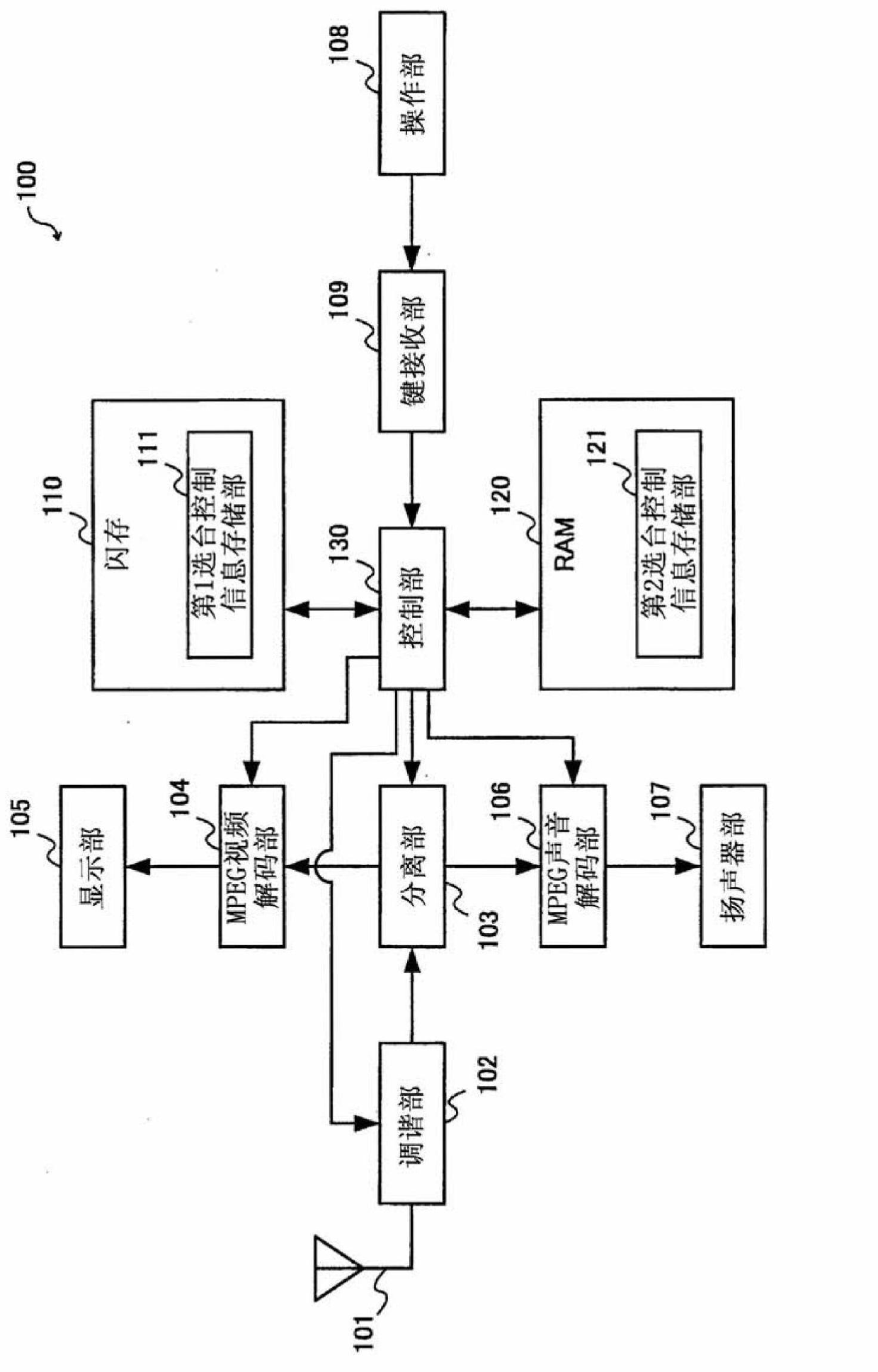
[0057] figure 1 It is a schematic block diagram showing the configuration of the digital broadcast receiving device 100 according to Embodiment 1 of the present invention. As shown in the figure, the digital broadcast receiving device 100 has an antenna 101, a tuner unit 102, a separation unit 103, an MPEG video decoding unit 104, a display unit 105, an MPEG audio decoding unit 106, a speaker unit 107, an operation unit 108, and a key receiving unit 109. , a flash memory 110 , a RAM (Random Access Memory) 120 , and a control unit 130 .
[0058] Antenna 101 receives digital broadcast signals, and supplies the received digital broadcast signals to tuner unit 102 .
[0059] The tuner unit 102 demodulates the digital broadcast signal received by the antenna 101 to generate a transport stream (hereinafter referred to as TS), and supplies the generated TS to the separation unit 103 .
[0060] The separation unit 103 separates the TS received by the tuner unit 102 to obtain video p...
Embodiment approach 2
[0130] Next, Embodiment 2 in the present invention will be described. In Embodiment 2, the information stored in the second tuning control information table 121 a is updated using TSs of channels other than the channel the user is viewing.
[0131] Figure 8 It is a schematic block diagram showing the configuration of the digital broadcast receiving device 200 according to the second embodiment. As shown in the figure, the digital broadcast receiving device 200 has an antenna 101, a tuner unit 102, a separation unit 103, an MPEG video decoding unit 104, a display unit 105, an MPEG audio decoding unit 106, a speaker unit 107, an operation unit 108, and a key receiving unit 109. , flash memory 110, RAM 120, control unit 230, auxiliary tuning unit 260, and buffer unit 261. Compared with Embodiment 1, the control unit 230, auxiliary tuning unit 260, and buffer unit 261 are different. Items are explained.
[0132] The auxiliary tuner unit 260 demodulates the digital broadcast si...
Embodiment approach 3
[0162] Next, Embodiment 3 in the present invention will be described. In Embodiment 3, similarly to Embodiment 2, the information stored in the second tuning control information table 121a is updated using TSs obtained for channels other than the channel the user is viewing. However, in Embodiment 3, the information stored in the second tuning control information table 121a is updated with respect to the channel starting a new program using the program time information.
[0163] Figure 11 It is a schematic block diagram showing the configuration of the digital broadcast receiving device 300 according to the third embodiment. As shown in the figure, the digital broadcast receiving device 300 has an antenna 101, a tuner unit 102, a separation unit 103, an MPEG video decoding unit 104, a display unit 105, an MPEG audio decoding unit 106, a speaker unit 107, an operation unit 108, and a key reception unit 109. , flash memory 110 , RAM 320 , control unit 330 , sub-tuner unit 260...
PUM
 Abstract
Description
Claims
Application Information
 - R&D Engineer
- R&D Manager
- IP Professional
- Industry Leading Data Capabilities
- Powerful AI technology
- Patent DNA Extraction
Browse by: Latest US Patents, China's latest patents, Technical Efficacy Thesaurus, Application Domain, Technology Topic, Popular Technical Reports.
© 2024 PatSnap. All rights reserved.Legal|Privacy policy|Modern Slavery Act Transparency Statement|Sitemap|About US| Contact US: help@patsnap.com