Electronic accelerator pedal

An electronic accelerator pedal and foot pedal technology is applied in the layout, transportation and packaging of power plant control mechanisms, vehicle components, etc., and can solve the problem of non-linear relationship between signal output, uneven operation intention output, and low driving operation accuracy. problem, to achieve the effect of good electromagnetic compatibility, improved driving operation accuracy, and simple structure

Active Publication Date: 2012-08-22
NO 70 INST OF CHINA NORTH IND GRP
View PDF5 Cites 5 Cited by
  • Summary
  • Abstract
  • Description
  • Claims
  • Application Information

AI Technical Summary

Problems solved by technology

However, the effective utilization rate of the internal potentiometer angle of the existing electronic accelerator pedal is low, and the theoretical pedal angle and signal output are not in a linear relationship, resulting in low driving operation accuracy and uneven output of operation intentions

Method used


Image

  • Electronic accelerator pedal
  • Electronic accelerator pedal
  • Electronic accelerator pedal

Examples


Embodiment Construction

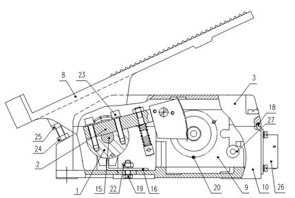
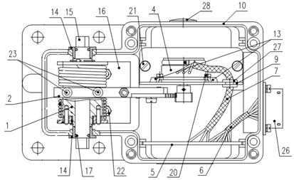
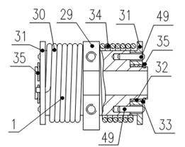
[0024] Such as Figure 1 to Figure 9As shown, an electronic accelerator pedal includes a spring bushing 1, a gear arm fan 2, a pedal box cover 3, a gear potentiometer 4, a circuit board 5, a No. I cable harness 6, a No. II cable harness 7, Pedal device 8, fixed plate 9, pedal seat 10, fixed piece 13, bushing 14, shaft 15, limit plate 16, small O-ring 17, large O-ring 18, bolt 19, screw 20, screw 21, nut 22, screw 23, electrical connector 26, pass coil 27 and screw plug 28; Pedal box cover 3 is made up of box cover 43, screw 44, snap ring 45, and box cover 43 is provided with through hole, and screw 44 is opening The grooved pan head does not come out of the screw, and the snap ring 45 is a cylinder rolled from a spring steel plate. The snap ring 45 is installed in the through hole of the box cover 43, and the outer circle is closely combined with the inner wall. The screw 44 is installed in the inner hole of the snap ring 45. , the joint surface of the pedal box cover 3 is pr...


PUM


Abstract

The invention relates to an electronic accelerator pedal which comprises a spring shaft sleeve (1), a toothed arm fan (2), a box cover (3) of a pedal plate, a gear potentiometer (4), a circuit board (5), a No. I wire cable bundle (6), a No. II wire cable bundle (7), a pedal device (8), a fixing plate (9), a pedal seat (10), a fixing piece (13), a bush (14), a shaft (15), a limiting plate (16), a small O-shaped ring (17), a big O-shaped ring (18), a bolt (19), a screw (20), a screw (21), a nut (22), a screw (23), an electric connector (26), an over coil (27) and a plug (28). The electronic accelerator pedal has the following advantages that: the structure is simple and compact, the reliability is high, and the electromagnetic compatibility is good; the electronic accelerator pedal is provided with a linear amplifying transmission system; the whole-process angle of foot pedaling corresponds to the whole process of the angle output of the potentiometer, and the signal output linearity is good; and the electronic accelerator pedal has the function of characteristic change of maximum torque output, so that a theoretical pedaling turn angle and the signal output are in a linear relationship, and the accuracy of driving operation is enhanced.

Description

[0001] technical field [0002] The invention belongs to the technical field of electronic control, and in particular relates to an electronic accelerator pedal. Background technique [0003] As everyone knows, in order to control the oil intake of the motor vehicle oil cylinder, and then control the rotating speed and power of the engine, to finally realize the control of the motor vehicle speed, an accelerator pedal is all provided in the motor vehicle cab. Most of the traditional accelerator pedals are mechanical accelerator pedals, which control the opening of the accelerator through connecting rods or cables. A series of actions are mechanical movements. Since the series of actions of this mechanical accelerator pedal are mechanical movements, Make its transmission precision and sensitivity not high, can't realize fuel saving and accurate control vehicle speed more. [0004] Due to the shortage of mechanical accelerator pedals, many enterprises have developed and produ...

Claims


Application Information

Patent Timeline
IPC IPC(8): B60K26/02
Inventor 郁国军王孝焦玉琴褚全红孟长江傅文林闫云艳
Owner NO 70 INST OF CHINA NORTH IND GRP
Why Eureka
Try Eureka