Supercharge Your Innovation With Domain-Expert AI Agents!

Display equipment and driving method thereof

A display device and device technology, applied in the direction of static indicators, optics, instruments, etc., can solve the problems of ripples, 2D image brightness reduction, 2D image visibility reduction, etc.

Active Publication Date: 2012-08-29
BOE TECH GRP CO LTD
View PDF4 Cites 5 Cited by
  • Summary
  • Abstract
  • Description
  • Claims
  • Application Information

AI Technical Summary

Problems solved by technology

[0006] Although the setting of BS improves the vertical viewing angle of the display device to a certain extent, the interaction between BS and BM will cause moire.
Therefore, when a 2D image is displayed on the display device, the visibility of the 2D image is greatly reduced due to the moiré.
In addition, since the BS is formed on the phase modulation panel 5 at the position corresponding to the pixel of the display panel 3, when a 2D image is displayed on the 3D display device, the brightness of the 2D image is also reduced due to the presence of the BS.

Method used


Image

  • Display equipment and driving method thereof
  • Display equipment and driving method thereof
  • Display equipment and driving method thereof

Examples


Embodiment Construction

[0028] The display device and its driving method proposed by the present invention are described in detail below with reference to the drawings and embodiments.

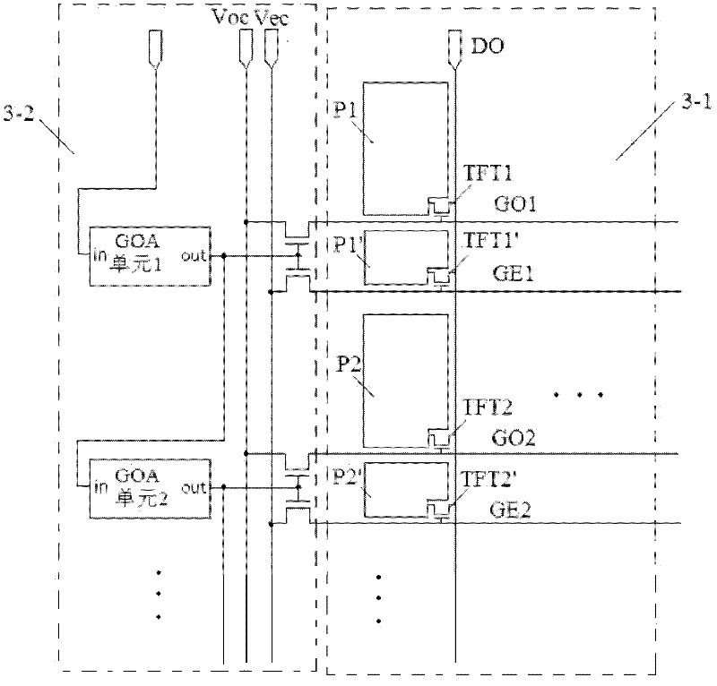
[0029] In this embodiment, each pixel electrode includes a main pixel electrode and an auxiliary pixel electrode as an example for description. The main pixel electrode is used for image display, and the auxiliary pixel electrode is used for forming a BS in 3D mode. The case of a plurality of main pixel electrodes and auxiliary pixel electrodes can be analogized, corresponding to adding a plurality of gate lines, a plurality of control TFTs and a plurality of control signal lines respectively. The driving method can also be deduced in the same way, which will not be described in detail here, and the groups used for image display and for forming BSs in 3D mode can be arbitrary.

[0030] A 2D / 3D display device according to an embodiment of the present invention includes a display panel, a gate driving device, a data dr...


PUM


Abstract

The invention discloses display equipment and a driving method thereof, which relate to the technical field of 2D / 3D display. The equipment comprises a display panel and a grid electrode driving device. Each pixel electrode comprises at least one main pixel electrode and at least one auxiliary pixel electrode, a grid line is arranged between two adjacent rows of pixel electrodes, and a grid line is arranged between every two parts of each divided pixel electrode. A data line is arranged between two adjacent lines of pixel electrodes, and each part of the pixel electrode on the same line is connected with the same data line. The grid electrode driving device is used for leading all pixel electrodes to input data signals in a 2D mode of the display panel. In a 3D mode of the display panel, a part of each pixel electrode is used for inputting the data signals, the remaining pixel electrode is not used for inputting the data signals, and black stripes are formed. According to the display equipment and the driving method of the display equipment disclosed by the invention, the black stripes are formed in the display panel, so that the equipment has a larger vertical angle of view, and additionally, the visibility and the display brightness are not affected.

Description

technical field [0001] The present invention relates to the field of display technology, in particular to a display device and a driving method thereof. Background technique [0002] Three-dimensional (3D) display has become a trend in the field of display. The basic principle of 3D display is that parallax produces stereo, even if people's left eye sees the image of the left eye, and the right eye sees the image of the right eye. pairs of stereo images. [0003] The 3D display technology based on polarized glasses is a more commonly used 3D display technology. Two left and right images are projected by the display, and the user uses polarized glasses matched with the display to distribute the left and right images to the left and right eyes respectively. Polarized glasses use lenses with different polarization directions to make the light emitted by the display produce different angles of polarization directions corresponding to the screen. [0004] Such as figure 1 As ...

Claims


Application Information

Patent Timeline
IPC IPC(8): G09G3/34G02B27/22H04N13/04
CPCG09G3/003G09G3/20G09G2300/0443G09G2310/063G09G2320/0209G02F1/134345G02B30/27
Inventor 张玉婷
Owner BOE TECH GRP CO LTD
Features
  • R&D
  • Intellectual Property
  • Life Sciences
  • Materials
  • Tech Scout
  • Unparalleled Data Quality
  • Higher Quality Content
  • 60% Fewer Hallucinations
Learn More