
Squirrel-cage rotor for induction motor

一种感应电动机、笼型转子的技术,应用在异步感应电动机、电气元件、机电装置等方向,能够解决转子可靠性未必能提高、制造工序变多、制造成本变高等问题

Inactive Publication Date: 2012-08-29
FANUC LTD
View PDF9 Cites 10 Cited by
  • Summary
  • Abstract
  • Description
  • Claims
  • Application Information

AI Technical Summary

Problems solved by technology

Therefore, in Japanese Patent Application Laid-Open No. 2-119557, the number of manufacturing steps increases, and the manufacturing cost also becomes higher.
In addition, in Japanese Patent Application Laid-Open No. 2011-10498, if the area of ​​the groove becomes larger, the thickness between the groove and the outer diameter becomes smaller, so the reliability of the rotor of Japanese Patent Laid-Open No. 2011-10498 may not be improved.

Method used


Image

  • Squirrel-cage rotor for induction motor
  • Squirrel-cage rotor for induction motor
  • Squirrel-cage rotor for induction motor

Examples


Embodiment Construction

[0024] Hereinafter, embodiments of the present invention will be described with reference to the drawings. In the following drawings, the same reference symbols are attached to the same components. For easy understanding, these drawings are appropriately changed in reduced scale.

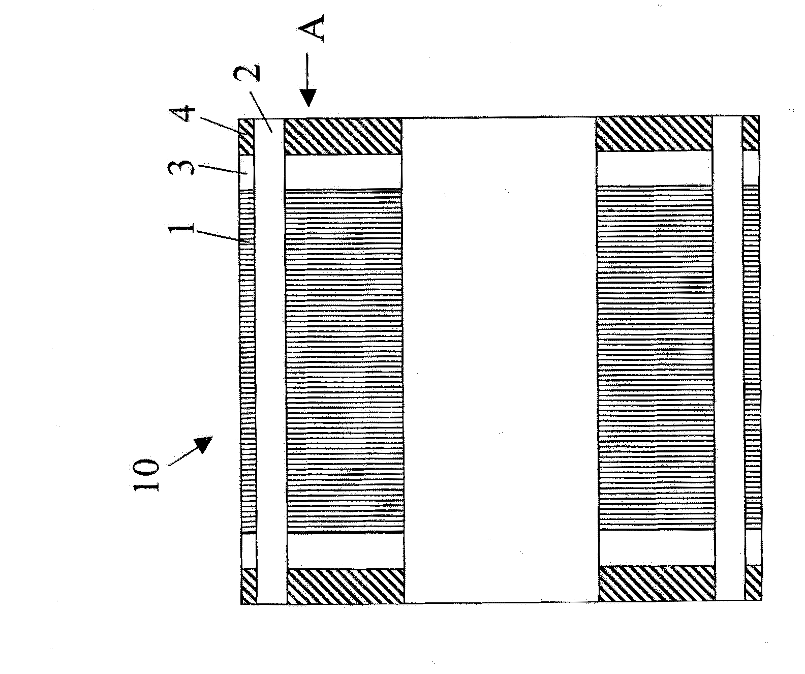
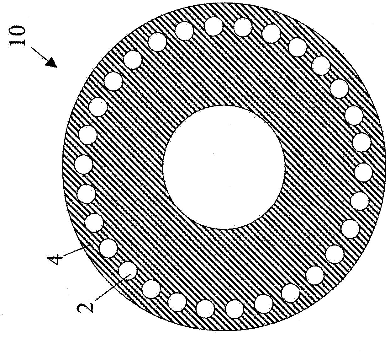
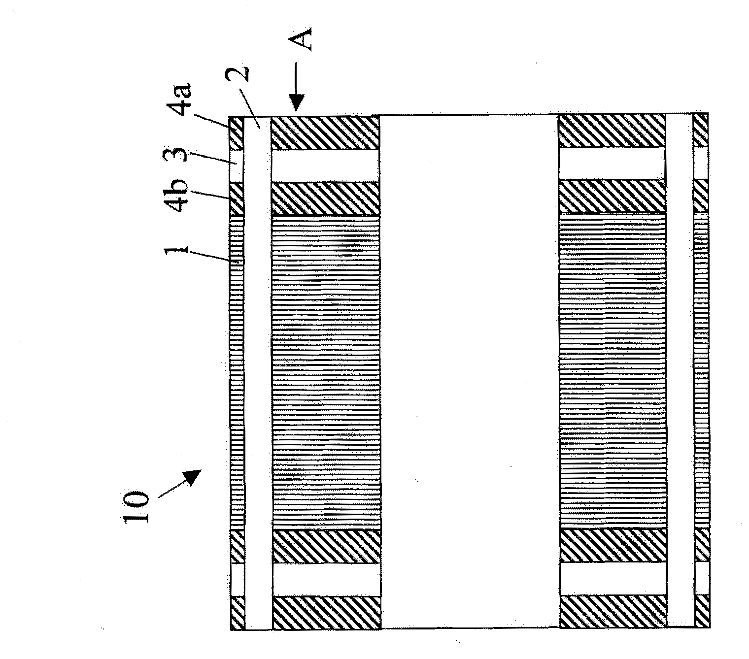
[0025] Figure 1a is a side sectional view of the cage rotor according to the first embodiment of the present invention, Figure 1b From Figure 1a The end view of the cage rotor viewed from the arrow A shown. Figure 1a The illustrated cage rotor 10 includes a rotor core 1 . The rotor core 1 as the core of the cage rotor 10 is formed of a general material such as a laminate of electromagnetic steel sheets. Furthermore, a plurality of slots (not shown) extending in the axial direction are formed in the rotor core 1 .

[0026] A conductor rod 2 made of copper or a copper alloy is inserted into each of these slots. The shape of the conductor rod 2 is roughly the same as the shape of the slot. lik...


PUM


Abstract

A squirrel-cage rotor includes a rotor core formed having a plurality of slots, a plurality of conductor bars inserted into the slots respectively and made of copper or copper alloy, two conductor end rings joined to the plurality of conductor bars on both end faces of the rotor core and made of copper or copper alloy and a reinforcing-member end ring attached to at least one of the conductor end rings and made of material having a specific strength greater than that of either copper or copper alloy. The plurality of conductor bars are arranged so as to extend through the conductor end rings and the reinforcing-member end ring. Consequently, the rotor can be manufactured by any manufacturing method but die-casting. Further, the conductor end rings can be reinforced with an easily-obtainable material and additionally, the junction of conductor end rings can be easily viewed from an outside.

Description

technical field [0001] This invention relates to cage rotors for induction motors. Background technique [0002] A cage-type rotor of an induction motor mainly includes: a rotor core; a plurality of rods passing through slot holes of the rotor core; and end rings joining the plurality of rods on both end faces of the rotor core. From the standpoint of manufacturing cost and material cost, many rods and end rings are integrally produced from aluminum by die-casting. [0003] In addition, in recent years, induction motors with high output and low heat generation have been demanded. Therefore, the conductor portion of the rotor of the induction motor may be made of a metal having a lower electrical resistance than aluminum, such as copper or a copper alloy. [0004] Furthermore, the motor is required to be increased in speed. However, since the melting point of copper or copper alloy is higher than that of aluminum, forming the conductor portion of the rotor by die casting m...

Claims


Application Information

Patent Timeline
Patent Type & Authority Applications(China)
IPC IPC(8): H02K17/16
CPCH02K17/16
Inventor 梶屋贵史前田尚志福田正干
Owner FANUC LTD
Learn More