Method and Apparatus for Vascular Anastomosis

a technology of vascular anastomosis and vascular endoscopy, which is applied in the field of methods and apparatus for vascular anastomosis, can solve the problems of microsurgical procedures that are time and resource-consuming, prone to complications, and local thrombosis, and achieve the effects of facilitating the stent stent securing or affixing, inhibiting or preventing the movement of the stent, and facilitating the maintenance of the vessel

Inactive Publication Date: 2012-11-01
THE BRIGHAM & WOMEN S HOSPITAL INC
View PDF5 Cites 42 Cited by
  • Summary
  • Abstract
  • Description
  • Claims
  • Application Information

AI Technical Summary

Benefits of technology

[0011]Embodiments of the present invention include expandable stents configured to be placed within two vessel ends to be joined, such that the stent can be configured to expand after being placed within the vessel ends to facilitate maintaining of the vessel ends in a coapted arrangement. Expanding the stent after placing it within the vessels can facilitate securing or affixing of the stent to the inside walls of the vessels, thereby inhibiting or preventing movement of the stent relative to the vessel walls. The stent can be expanded by using one or more balloons provided within the stent, a tensioned filament, string, or wire, or the like. The stent can also be formed using a shape-memory material, such that the stent in a compacted state can expand when heated up to body temperature after insertion in the vessel ends.
[0012]Self-expanding stents can also be used, where such stents can be held in a compacted or compressed state using one or more retainers, and then allowed to expand after being placed in the vessel ends by releasing, cutting, or otherwise deactivating the retainers. The self-expanding stents can include one or more retainers provided at or near each end of the stent, such that each end of the stent can be expanded at different times. In this manner, one end of the stent can be placed in a first vessel end and expanded to anchor it within the first vessel. The unexpanded end can then be placed into an opening of the second vessel end, and expanded after the two vessel ends are coapted to secure the stent within the second vessel and hold the ends of the vessels together through frictional forces and mechanical anchoring of the stent against the inner vessel walls. A tissue adhesive or other substance can optionally be applied over the joined tissue portions to improve the adherence and / or sealing of the vessels.
[0013]A sleeve can also be provided over the tissue junction and around the inserted stent, such that the vessel walls are held between the inner expanded stent and the outer sleeve. The sleeve can be substantially cylindrical in shape, and can be provided in a hinged configuration that includes two sleeve portions pivotally attached to one another e.g., pivoting along a line that is substantially parallel to the longitudinal axis of the cylinder. The hinged sleeve can include a securing arrangement configured to hold the two sleeve portions in the shape of a hollow cylinder when the sleeve portions are placed around the vessels in a closed configuration. In certain embodiments, the sleeve can be formed using a deformable material that can be pressed in place around the coapted vessels and supporting stent. The inner diameter of the sleeve can be constant, or it can vary along the longitudinal axis of the sleeve. For example, the end regions of the sleeve can have different internal diameters to facilitate joining of two vessels having different sizes and / or or wall thicknesses. The central portion of the sleeve can also be provided with a larger internal diameter than that of the end portions. Such a larger central diameter can better accommodate the coapted ends of the vessels when the sleeve is placed around the joined vessels.
[0015]Further embodiments of the invention can facilitate formation of side-to-end grafts, e.g., for affixing the end of a vessel to an opening in a wall of a larger vessel or a biological organ. For example, a stent can be provided that includes a proximal end provided in a form of a conventional expandable stent and configured to be inserted into and affixed to an end of a first vessel. A distal end of the stent can be provided with a plurality of extensions configured to extend outward from the longitudinal axis of the stent in the expanded state. The extensions can be held in a compressed or compacted state before the distal end is inserted through a wall of a larger vessel or organ, using one or more retainers. The retainers can be cut, released, or otherwise deactivated after the distal end of the stent is inserted through the wall of the larger vessel or organ, allowing the extensions to expand and press against the inner side of the wall, thereby securing the first vessel to the wall. The extensions can have different lengths, e.g., to allow the expanded extensions to better conform to the shape of the inner wall of the larger vessel or organ.

Problems solved by technology

Microsurgical procedures tend to be time and resource consuming, technically demanding, and prone to complications.
Technical imperfections arising from the anastomosis can lead to local thrombosis and eventual loss of the transferred tissue.
In addition, the apparatus used to deploy the coupler rings in the Synovis® coupler system is cumbersome and difficult to operate in a confined space, which is often required in vascular anastomoses.
Nevertheless, the Synovis® coupler system can shorten the time needed to perform many microvascular anastomoses, and can also decrease the likelihood of forming an undesirable venous thrombosis.

Method used


Image

  • Method and Apparatus for Vascular Anastomosis
  • Method and Apparatus for Vascular Anastomosis
  • Method and Apparatus for Vascular Anastomosis

Examples


Embodiment Construction

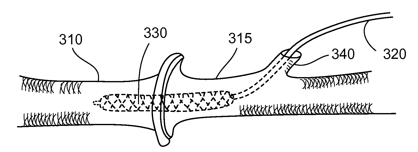
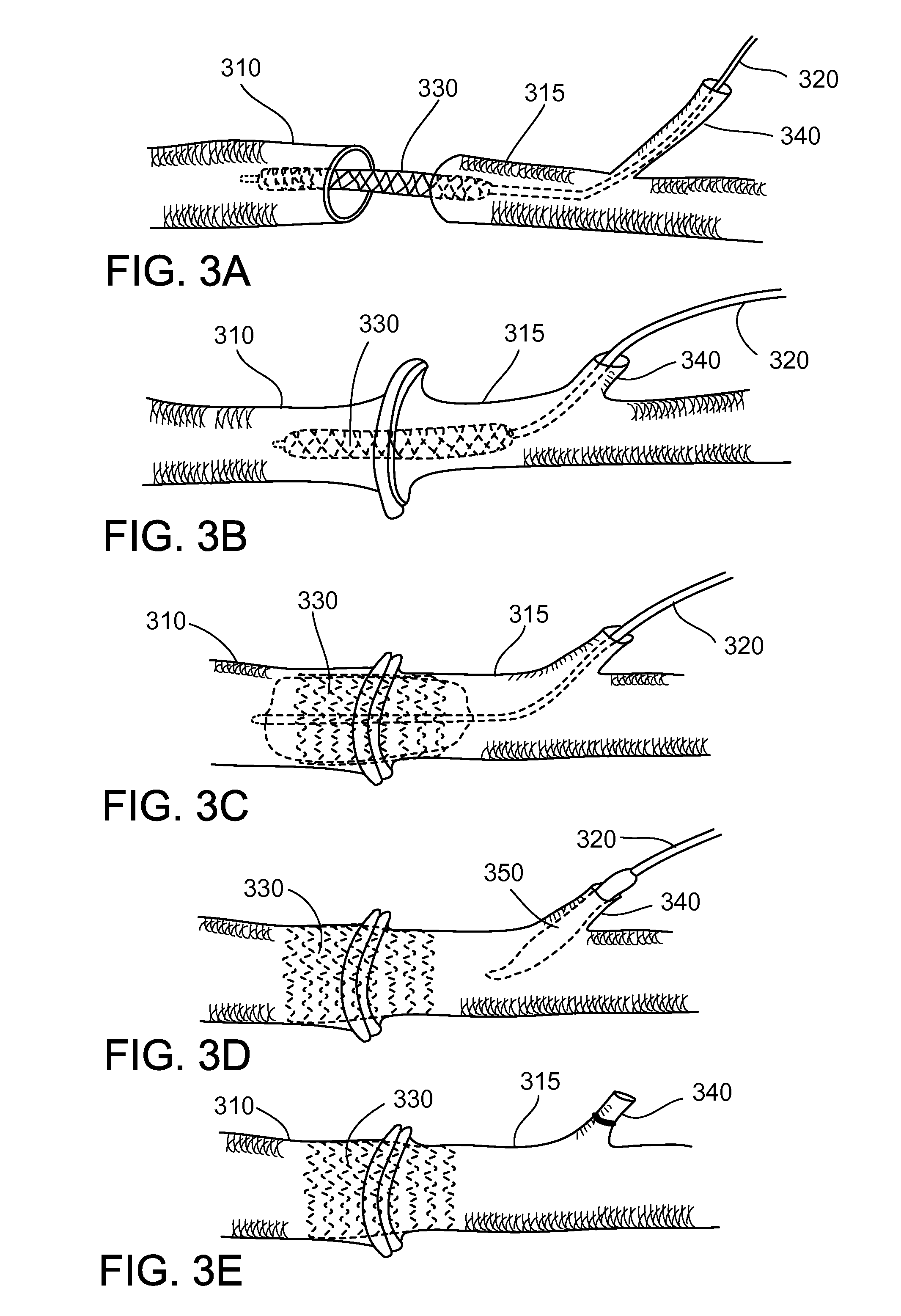
[0031]An exemplary method and apparatus for performing an anastomosis are shown in FIGS. 3A-3E. In FIG. 3A, the ends of two vessels 310, 315 to be joined are shown. A catheter 320 or other device that includes a balloon-deployable stent 330 is introduced through a side branch 340, such that the stent 330 passes through both vessel ends. The ends of the vessels 310, 315 are then coapted against each other over the unexpanded stent 330, as shown in FIG. 3B. The stent 330 is then expanded, as shown in FIG. 3C, and the catheter 320 with the deflated balloon apparatus 350 can then be withdrawn through the sidebranch 340, as shown in FIG. 3D. FIG. 3E shows the side branch 340 being sealed off after the catheter 320 and the balloon 350 are withdrawn.

[0032]A typical microvascular vessel 310, 315 that can require anastomosis during microsurgical procedures can have an outer diameter between about 1 mm and 4 mm. The expanded diameter or size of the stent 330 can be slightly larger than the di...


PUM


Abstract

Methods and apparatus can be used for anastomosis, and more specifically, for joining two vascular vessels, e.g., arterial or venous vessels or the like, using a stent.

Description

CROSS REFERENCE TO RELATED APPLICATION[0001]The present application claims priority from U.S. Provisional Patent Application Ser. No. 61 / 260,969, filed on Nov. 13, 2009, the disclosure of which is incorporated herein by reference in its entirety.FIELD OF THE INVENTION[0002]The present disclosure is directed to methods and apparatus for vascular anastomosis, and more particularly for methods and apparatus for joining blood vessels or other tissue structures using a stent-based device.BACKGROUND INFORMATION[0003]Microsurgical procedures are often a preferred or necessary surgical modality for reconstructing difficult defects. They often require anastomosis (joining) of small vascular vessels, e.g., veins and arteries, which can be damaged or severed. Such vessels typically have a diameter between about 0.5 and 1.5 mm.[0004]Anastomoses are typically hand-sewn under a microscope using about 8-10 sutures, and the distance between adjacent sutures is typically about 0.3 to 0.4 mm. An exem...

Claims


Application Information

Patent Timeline
Patent Type & Authority Applications(United States)
IPC IPC(8): A61B17/11A61F2/82
CPCA61B17/11A61F2/82A61B2017/1132A61B2017/1107
Inventor GUO, LIFEI
Owner THE BRIGHAM & WOMEN S HOSPITAL INC
Why Eureka
Try Eureka