
Control apparatus for hybrid vehicle

A hybrid vehicle and control device technology, which is applied in the direction of hybrid vehicle, power device, transmission control, etc., and can solve problems such as shock and vibration

Active Publication Date: 2014-12-17
JATCO LTD
View PDF3 Cites 0 Cited by
  • Summary
  • Abstract
  • Description
  • Claims
  • Application Information

AI Technical Summary

Problems solved by technology

[0004] However, for example, when continuously changing from the 5th speed to the 4th speed and the 3rd speed, if the slip control of the second clutch is simply terminated based on the fact that the first shift is completed, the input torque to the transmission may fluctuate, and the Will produce shock vibration

Method used


Image

  • Control apparatus for hybrid vehicle
  • Control apparatus for hybrid vehicle
  • Control apparatus for hybrid vehicle

Examples


Embodiment 1

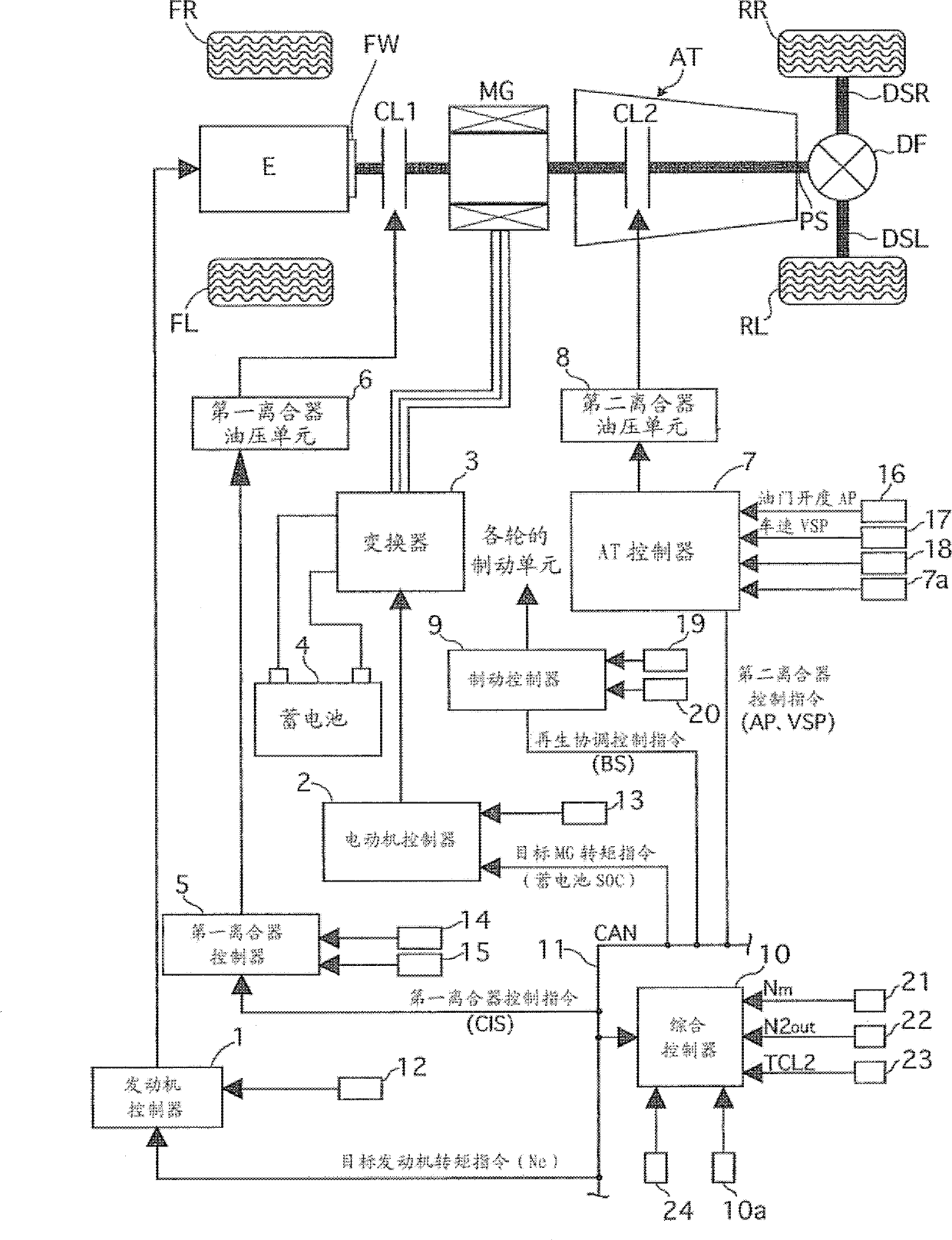
[0052] First, the drive train configuration of the hybrid vehicle will be described. figure 1 It is an overall system diagram showing a rear-wheel drive hybrid vehicle to which the engine start control device of the first embodiment is applied. Such as figure 1 As shown, the drive system of the hybrid vehicle in Embodiment 1 has: engine E, flywheel FW, first clutch CL1, motor generator MG, second clutch CL2, automatic transmission AT, transmission shaft PS, differential DF, left Drive shaft DSL, right drive shaft DSR, left rear wheel RL (drive wheel), right rear wheel RR (drive wheel). In addition, FL is a left front wheel, and FR is a right front wheel.

[0053] The engine E is a gasoline engine or a diesel engine, and the valve opening degree of a throttle valve and the like are controlled based on a control command from an engine controller 1 described later. In addition, a flywheel FW is provided on the engine output shaft.

[0054] The first clutch CL1 is a clutch ins...


PUM


Abstract

A control apparatus of a hybrid vehicle provided with an engine (E), a motor (MG), an automatic transmission (AT) performing a shift by engaging / disengaging a plurality of engagement elements, a first clutch (CL1) arranged between the engine (E) and the motor (M) for transmitting / cutting a driving force between the engine (E) and the motor (M) and a second clutch (CL2) arranged between the motor (M) and driving wheels (RL, RR) for transmitting / cutting a driving force from the motor (M) to the driving wheels (RL, RR), has a slip control section (400) that controls the second clutch (CL2) to a slip state during the shift of the automatic transmission (AT). In a case of a successive shift in which a current shift and a succeeding shift are successively performed, the slip control section gradually increases an engagement pressure of the second clutch (CL2) when changing the slip state of the second clutch (CL2) to a fully engaged state after the current shift is completed and before the succeeding shift is completed.

Description

technical field [0001] The present invention relates to a control device for a hybrid vehicle including a coupling element between an electric motor and drive wheels. Background technique [0002] As a hybrid vehicle, the technology of Patent Document 1 is disclosed. This publication discloses a configuration in which a motor generator is provided between the engine and the stepped automatic transmission, and a first clutch for clutching and disengaging the driving force between the engine and the motor generator is provided, and the motor generator and the motor generator are connected to each other. The second clutch that engages and engages the driving force between the automatic transmission. In addition, at the time of shifting without starting the engine, slip control of the second clutch is performed to suppress shifting vibration. [0003] Patent Document 1: (Japanese) Unexamined Patent Application Publication No. 2009-214640 [0004] However, for example, when co...

Claims


Application Information

Patent Timeline
Patent Type & Authority Patents(China)
IPC IPC(8): B60W20/00B60W30/20B60L50/16
CPCB60W20/00F16H61/686B60W10/115B60W2710/1022F16H2061/0462B60W2710/1011B60W2710/025B60W10/02B60W2710/1005B60W2710/023B60W30/19F16H61/061F16H2061/0444B60K6/547B60W20/30
Inventor 铃木正己山中史博
Owner JATCO LTD
Learn More