High speed railway sound barrier insertion loss calculation method

An insertion loss, high-speed railway technology, used in computing, special data processing applications, instruments, etc., can solve the difference in frequency characteristics of sound sources, increase the proportion of pantograph noise and aerodynamic noise, and determine the equivalent position of the sound source in a single location. The position of the track surface, etc.

Active Publication Date: 2012-10-03
CHINA RAILWAY DESIGN GRP CO LTD
View PDF0 Cites 11 Cited by
  • Summary
  • Abstract
  • Description
  • Claims
  • Application Information

AI Technical Summary

Problems solved by technology

For high-speed railways with complex sound source composition, on the one hand, the frequency characteristics of the sound source are significantly different from those of ordinary speed railways; The proportion of pantograph-catenary noise and aerodynamic noise has increased, and the equivalent position of the sound source is still single. It is no longer suitable to determine the position on the rail surface
The actual measurement results show that the insertion loss of high-speed railway sound barrier calculated according to the existing method is very different from the actual noise reduction effect, which brings great difficulty to the engineering design and also makes it difficult for the environmental protection acceptance of the completed high-speed railway

Method used


Image

  • High speed railway sound barrier insertion loss calculation method
  • High speed railway sound barrier insertion loss calculation method
  • High speed railway sound barrier insertion loss calculation method

Examples


Embodiment

[0040] Example, Calculation of the insertion loss of the sound barrier proposed to set up the sound barrier in Village A near the high-speed railway

[0041] Proposed case of village A distance: Village A is close to a high-speed railway. It is a one-story building. The shortest distance from the center line of the outer rail of the line is 30m; It is 1.2m above the ground, and it is proposed to take noise control measures to set up a 2.05m high sound barrier above the rail surface. The horizontal distance between the sound barrier and the center line of the outer line of the railway is 3.45m. The theoretical noise reduction effect of the sound barrier is calculated by inserting the sound barrier loss.

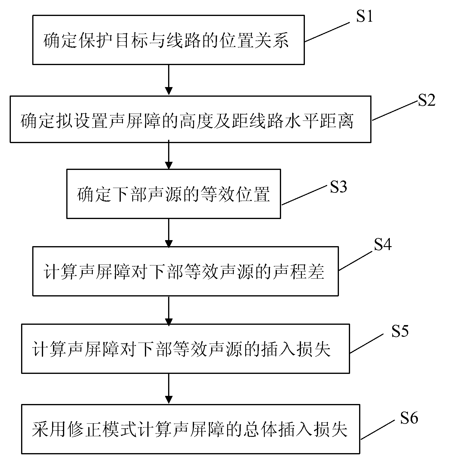
[0042] The specific calculation steps are as follows:

[0043] S1. Determine the positional relationship between the protection target and the line

[0044] The horizontal distance l between the protection target and the center of the railway line 1 =30m;

[0045] The heig...


PUM


Abstract

The invention discloses a high speed railway sound barrier insertion loss calculation method, which is provided according to a high speed railway sound source combination characteristic, a spectrum characteristic and a transmission characteristic, and aims to overcome the shortcomings in the conventional sound barrier insertion loss calculation. The high speed railway sound barrier insertion loss calculation method is applied to acoustic design of a high speed railway sound barrier, so that a theoretical noise reduction result of the high speed railway sound barrier can be calculated. The method comprises the following technical steps of: S1, determining a position relation between a protection target and a line; S2, determining a sound barrier height planned to be set and a horizontal distance from the line; S3, determining an equivalent position of a lower sound source; S4, calculating a sound path difference of the sound barrier to the lower equivalent sound source; S5, calculating insertion loss of the sound barrier to the lower equivalent sound source; and S6, calculating the total insertion loss of the sound barrier by adopting a correction mode.

Description

technical field [0001] The invention relates to engineering design of railway sound barriers, in particular to a calculation method for the noise reduction effect of high-speed railway sound barriers. Background technique [0002] In the existing engineering design of railway sound barriers, in order to calculate the theoretical noise reduction effect of different heights of sound barriers, and then determine the optimal setting height of the sound barriers on this basis, the "Technical Guidelines for Environmental Impact Assessment (Acoustic Environment)" and " Infinite length sound barrier prediction model recommended in Technical Specifications for Acoustic Design and Measurement of Sound Barriers. The main parameters involved in this prediction model are the equivalent position and equivalent frequency of the sound source. The equivalent position of the sound source is selected at the position of the railway track, and the equivalent frequency is selected as 500Hz. In t...

Claims


Application Information

Patent Timeline
Patent Type & Authority Applications(China)
IPC IPC(8): G06F17/50E01F8/00
Inventor 潘晓岩苏卫青
Owner CHINA RAILWAY DESIGN GRP CO LTD
Why Eureka
Try Eureka