Sensor housing and latching mechanism for sensor housing

A sensor and housing technology, applied in the field of component housing mechanisms, quick connectors or other system components, which can solve complex design requirements and increase costs.

Active Publication Date: 2016-06-08
TI GRP AUTOMOTIVE SYST LLC
View PDF14 Cites 0 Cited by
  • Summary
  • Abstract
  • Description
  • Claims
  • Application Information

AI Technical Summary

Problems solved by technology

Alternatively, adding sensing elements to components such as fuel tank flanges has complex design requirements and increased cost

Method used


Image

  • Sensor housing and latching mechanism for sensor housing
  • Sensor housing and latching mechanism for sensor housing
  • Sensor housing and latching mechanism for sensor housing

Examples


Embodiment Construction

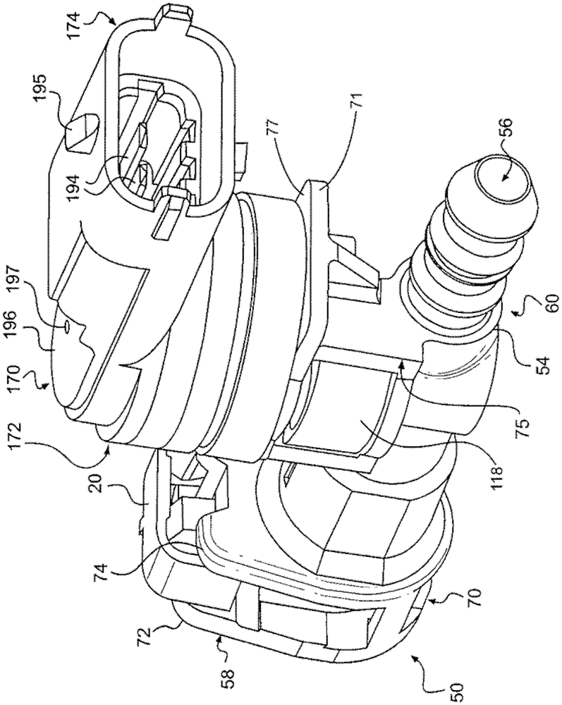
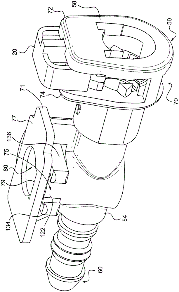
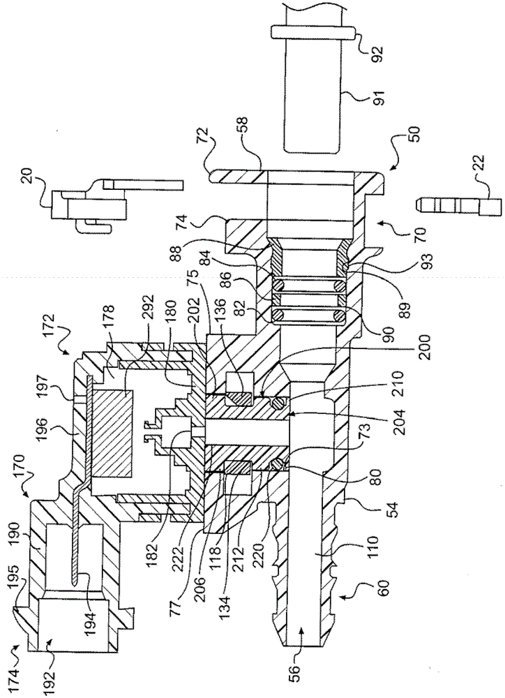
[0027] Figure 1 to Figure 11 Illustrated is a quick connector for a fluid system with an attached sensor housing that can house various mechanisms adapted to identify operating parameters of the fluid system. In its broadest aspects, the present disclosure is applicable to any element of a fluid system to which it is considered desirable to attach an induction mechanism contained within a housing.

[0028] The sensor housing may be removably attached to a mating portion on another structure, such as a quick connector body in a fuel line. An attachment mechanism may be used to secure the sensor housing to the mating part. The sensor housing is attached to the mating portion in a manner that prevents fluid leakage. The sensor disposed within the sensor housing can be any suitable sensor, such as a fluid pressure sensor or a temperature sensor.

[0029] turn to Figure 1 to Figure 3 , which illustrates the connector body 50 of the quick connector. For the purpose of illustr...


PUM


Abstract

A sensor housing and a latch mechanism for the sensor housing are disclosed. A removable sensor housing for connection to a structure in a fluid system, such as a quick connector body, is disclosed. The sensor housing is removably attached to a mating portion on another structure. The sensor housing includes a shaft inserted into a hole in the other structure, with a seal therebetween. An attachment mechanism is used to secure the sensor housing to the structure. An alternative mechanism is disclosed. In some forms, the sensor housing is configured to be positioned in a fixed relationship relative to other structures.

Description

[0001] Cross References to Related Applications [0002] This application claims the benefit of U.S. Provisional Application No. 61 / 470,838, filed April 1, 2011, entitled "Sensor Housing and Latching Mechanism for a Sensor Housing," under Title 35USCSec.119(e), the entirety of which is incorporated herein by reference as explained. technical field [0003] The present invention relates to fluid systems such as those that include quick connectors that connect rigid tubing to flexible hoses or other system components. More specifically, the present invention relates to a quick connector or other system component that includes a removable component housing mechanism for sensing conditions within the system. Background technique [0004] Quick connectors are commonly used to provide a permanent but separable connection between rigid pipe and flexible hose or other components. Such connections are exemplified in US Patent Nos. 5,161,832; 5,324,082; 5,423,577; 5,586,792; 5,626,3...

Claims


Application Information

Patent Timeline
Patent Type & Authority Patents(China)
IPC IPC(8): G01D11/24G01D11/20F16L37/088
CPCF16L41/008G01D11/245G01L19/003F16L2201/10G01K1/08F16L37/0885F16L37/00B60R16/02B60R16/00
Inventor 吉姆·凯林理查德·M·派普斯蒂芬·H·冈德森
Owner TI GRP AUTOMOTIVE SYST LLC
Why Eureka
Try Eureka