Power management apparatus

A power management device and power device technology, which are applied to output power conversion devices, pulse processing, electrical components, etc., can solve problems such as incorrect shutdown, startup, and shutdown of electronic devices, and achieve the effect of preventing automatic opening and closing.

Inactive Publication Date: 2015-01-21
NANNING FUGUI PRECISION IND CO LTD
View PDF3 Cites 0 Cited by
  • Summary
  • Abstract
  • Description
  • Claims
  • Application Information

AI Technical Summary

Problems solved by technology

However, when the on-off key is pressed for a long time due to external force or damage, the input end of the NAND logic gate connected to the on-off key will be in a high potential state for a long time, so that when the electronic device is turned on, the The other input terminal of the NAND logic gate will also generate a high potential, so that the output terminal of the NAND gate will correspondingly generate a low potential to stop the power supply to the electronic device, causing the electronic device to be closed by mistake
If the switch key is still in the pressed state at this time, so that the input terminal of the NAND gate continues to maintain a logic value of 1, and the other input terminal produces a logic 0 because the power supply stops supplying power to the electronic device, then the output terminal will output a high potential again. (i.e. logic 1) and restart the electronic device, so that the electronic device will be turned on and off repeatedly

Method used


Image

  • Power management apparatus
  • Power management apparatus

Examples


Embodiment Construction

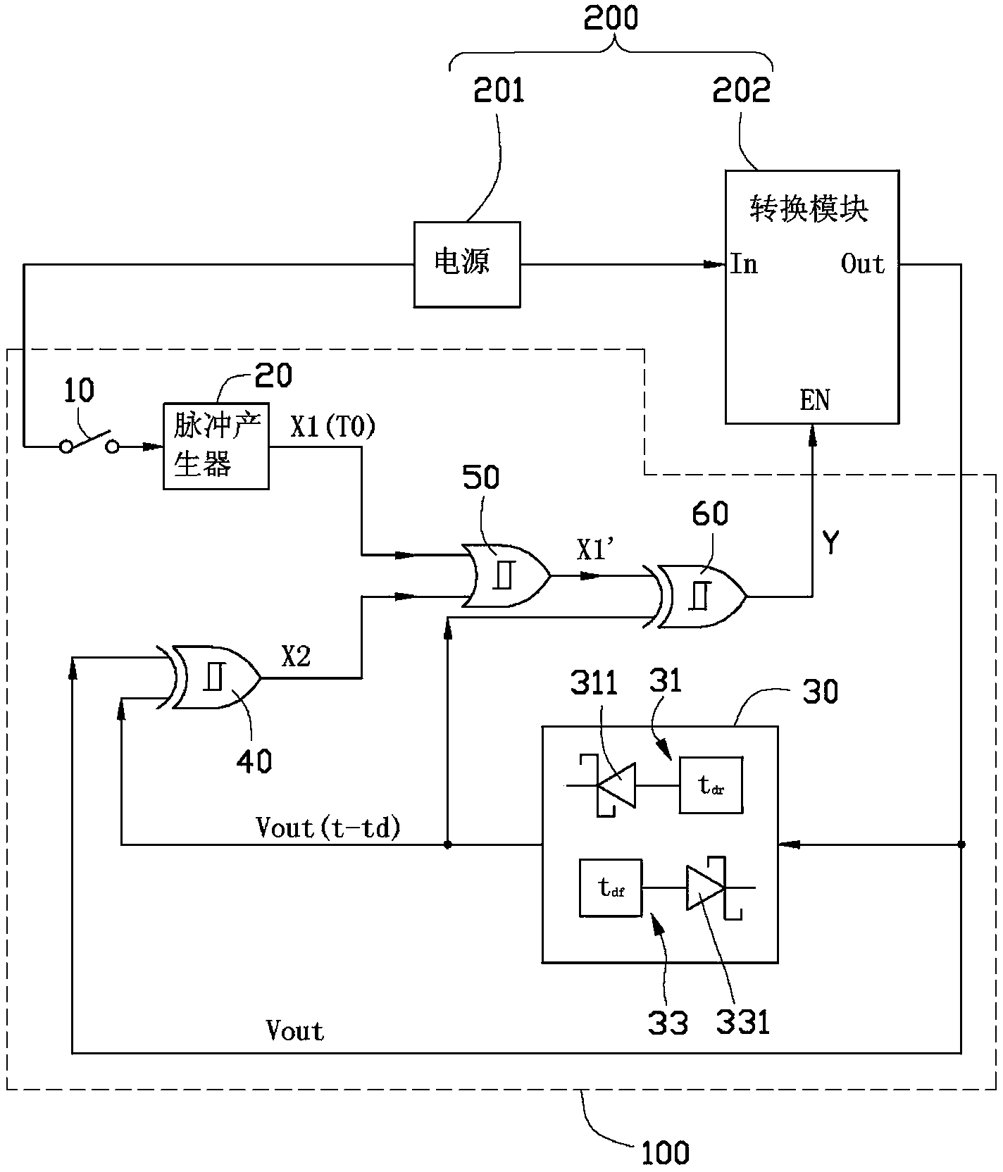
[0012] see figure 1 As shown, the power management device 100 according to the preferred embodiment of the present invention can be used to control the power supply device 200 to supply power to an existing electronic device (not shown in the figure), such as a TV set-top box.

[0013] The power supply device 200 includes a power supply 201 and a conversion module 202 connected to the power supply 201 , the conversion module 202 is used to convert the voltage provided by the power supply 201 into a rated voltage of the electronic device under the trigger of the power management device 100 to supply the electronic device. The conversion module 202 includes an input pin In, an output pin Out, and an enable pin EN, and is connected to the power supply 201 through the input pin In, and connected to the power management device 100 through the enable pin EN, so that the power management device Under the trigger of 100, the voltage connected to the input pin In is converted into the ...


PUM


Abstract

A power management device for controlling a power supply device includes a pulse generator, a delay unit, a first XOR gate, an OR gate, and a second XOR gate. The pulse generator generates a pulse signal, the delay unit, the first XOR gate, the OR gate, and the second XOR gate cooperatively generate an enabling signal corresponding to the pulse signal to enable and disable the power supply, and receive an output voltage of the power supply device as a feedback signal. Upon receiving the feedback signal, the power management device can stay at correct enabled and disabled statuses of the power supply device.

Description

technical field [0001] The invention relates to a power management device, in particular to a power management device with a stable switch state. Background technique [0002] The general actuation principle of the switch button of the existing electronic device is to generate a pulse signal by pressing the switch button, and the microcontroller built in the electronic device receives the pulse signal to control the power supply to supply or cut off the power to the electronic device. However, when using a microcontroller as a switch control element, it is necessary to burn the source code of the switch control program into the microcontroller in advance, which is not only complicated, but also costly. Therefore, a switching device that implements power management through hardware design without using a control program is further produced. [0003] The existing method of switching devices that implement power management through hardware is usually: one input end of an XOR l...

Claims


Application Information

Patent Timeline
Patent Type & Authority Patents(China)
IPC IPC(8): H02M1/36
CPCH02M1/36H03K5/1254
Inventor 罗文信
Owner NANNING FUGUI PRECISION IND CO LTD
Why Eureka
Try Eureka