Electronic control valve with circulating air guide function

An electronic control and valve technology, applied in the direction of valve lift, valve details, valve device, etc., can solve the problems of easy damage, single function and inconvenience of the air guide valve, and achieve the effect of improving the protection effect

Inactive Publication Date: 2021-02-05
JIANGSU BOTWAY FLUID TECH CO LTD
View PDF3 Cites 0 Cited by
  • Summary
  • Abstract
  • Description
  • Claims
  • Application Information

AI Technical Summary

Problems solved by technology

[0003] When using a valve for ventilation, because the passage of gas is often accompanied by high heat and high flow rate, the interior of the valve will be in a state of high temperature and high pressure. It will not always be consistent with the flow rate. In special cases, it will exceed the specified value on the valve. At this time, if the transmission air guide valve is used, the traditional air guide valve has a single function. If the ventilation volume to be used is set in advance Finally, even if it is necessary to change the flow rate in a small area, manual operation is required, which is very inconvenient. At the same time, the traditional valve has no obvious control ability for the internal heat of the valve, and it will be more easily damaged under special circumstances.

Method used


Image

  • Electronic control valve with circulating air guide function
  • Electronic control valve with circulating air guide function
  • Electronic control valve with circulating air guide function

Examples


Embodiment 1

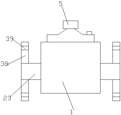
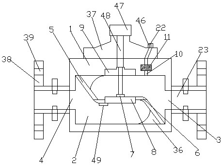
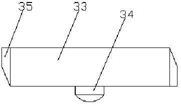
[0042] see Figure 1-8 , according to an embodiment of the present invention, an electronically controlled valve with circulating air guide includes a valve housing 1, a cavity 2 is opened in the valve housing 1, and inlets and outlets are respectively provided at both ends of the cavity 2. Gas port 3 and gas outlet 4, both ends in the cavity 2 are fixed with a sealing swash plate 5, and the end of the sealing swash plate 5 away from the inner wall of the cavity 2 is fixed with a transverse sealing plate 6, so A sealing cover 8 is detachably arranged between the two transverse sealing plates 6, and the sealing cover 8 includes a sealing connecting plate 33, and a displacement sensor 34 is arranged below the sealing connecting plate 33, and the sealing connecting plate 33 Elastic seals 35 are provided on both sides of the cavity, a placement cavity 9 is provided on the top of the cavity 2, a connecting block 7 is provided on the sealing cover 8, and a connecting block 7 is prov...

Embodiment 2

[0045] Such as Figure 6 As shown, the pipe fixing plate 27 includes an arc-shaped splint 31, and an arc-shaped elastic pad 32 is provided on the inner arc of the arc-shaped splint 31 to improve its fixing effect.

Embodiment 3

[0047] Such as figure 2 As shown, arc-shaped deflectors 36 are connected to one side of the sealing sloping plate 5 in the cavity 2 to increase the smoothness of air flow.


PUM


Abstract

The invention discloses an electronic control valve with a circulating air guide function. The valve comprises a valve shell, a cavity is formed in the valve shell, an air inlet and an air outlet areformed in the two ends of the cavity correspondingly, sealing inclined plates are fixedly arranged at the two ends in the cavity correspondingly, and transverse sealing plates are fixedly arranged atthe ends, away from the inner wall of the cavity, of the sealing inclined plates. A sealing cover plate is detachably arranged between the two transverse sealing plates and comprises a sealing connecting plate, a displacement sensor is arranged below the sealing connecting plate, elastic sealing sheets are arranged on the two sides of the sealing connecting plate, a containing cavity is formed inthe top of the cavity, a connecting block is arranged on the sealing cover plate, and a control device is arranged at the top of the valve shell. An air release port is formed in the valve shell and located on one side of the inner top of the air inlet. An automatic control device is arranged on the air release port. The valve has the beneficial effects that device structure is simple, use is convenient, the high-pressure state in the valve can be effectively reduced, the pressure of the valve is reduced, air release of the valve is facilitated, automatic control is achieved, and the safety isbetter.

Description

technical field [0001] The invention relates to the technical field of electronically controlled valves, in particular to an electronically controlled valve with circulating air guide. Background technique [0002] Valves are pipeline accessories used to open and close pipelines, control flow direction, adjust and control the parameters (temperature, pressure and flow) of the conveying medium. According to its function, it can be divided into shut-off valve, check valve, regulating valve, etc., which are the control components in the fluid delivery system, with the functions of cut-off, adjustment, flow diversion, prevention of reverse flow, voltage stabilization, diversion or overflow pressure relief, etc. . Valves used in fluid control systems, from the simplest globe valve to various valves used in extremely complex automatic control systems, have a wide variety of varieties and specifications, and can be used to control air, water, steam, various corrosive media, mud, e...

Claims


Application Information

Patent Timeline
Patent Type & Authority Applications(China)
IPC IPC(8): F16K1/00F16K1/32F16K31/04F16K37/00F16K27/02F16K27/08F16K25/00
CPCF16K1/00F16K1/32F16K31/04F16K37/00F16K37/0091F16K27/02F16K27/08F16K25/00
Inventor 吴连峰胡斌刘荣霞邱琳熙张啸周游
Owner JIANGSU BOTWAY FLUID TECH CO LTD
Why Eureka
Try Eureka