Tensioning and cushioning units for traction gear drives

A buffer unit and traction mechanism technology, applied in transmission, machine/engine, mechanical equipment, etc., can solve the problem that the buffer characteristics cannot be adjusted accurately, and achieve the effect of compact structure, space saving and assembly cost reduction.

Active Publication Date: 2016-09-14
SCHAEFFLER TECH AG & CO KG
View PDF9 Cites 0 Cited by
  • Summary
  • Abstract
  • Description
  • Claims
  • Application Information

AI Technical Summary

Problems solved by technology

However, its cushioning properties cannot be precisely adjusted and can only cushion small forces

Method used


Image

  • Tensioning and cushioning units for traction gear drives
  • Tensioning and cushioning units for traction gear drives
  • Tensioning and cushioning units for traction gear drives

Examples


Embodiment Construction

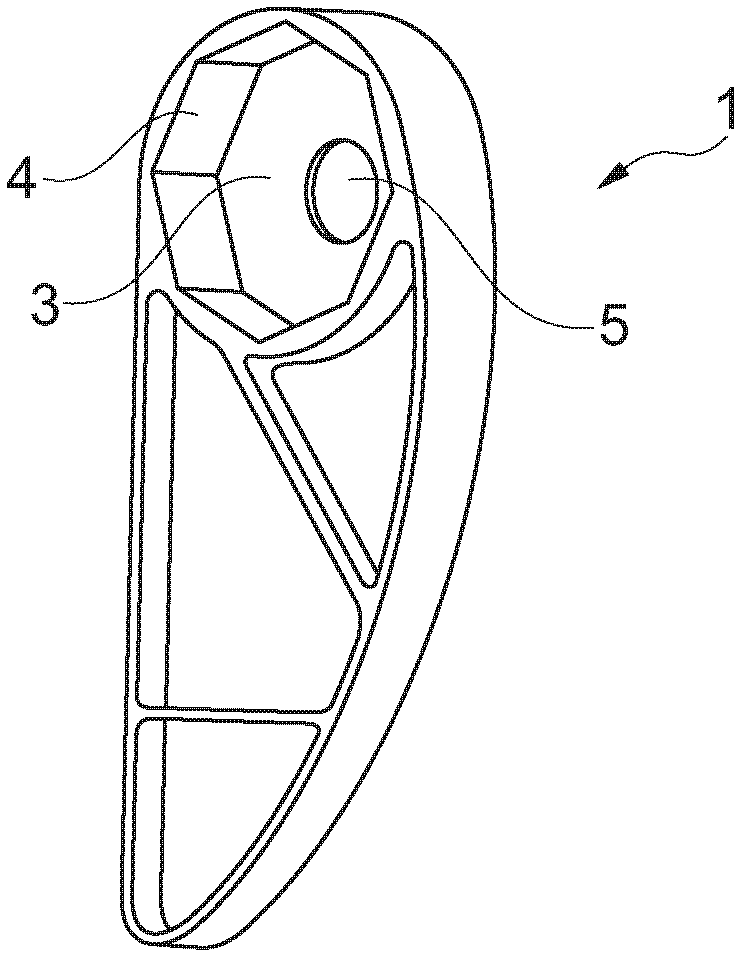
[0035] exist figure 1 Shown is a tensioning rail 1 into which a tensioning and damping unit 2 can be inserted, see Figure 5 and 6 . In connection with this, the tensioning rail 1 has a recess 3 with an octagonal inner profile 4 .

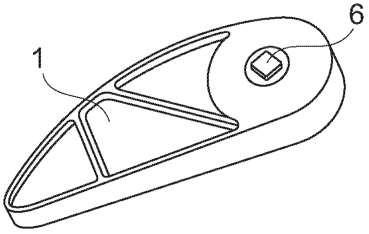
[0036] The tensioning rail 1 is made of plastic. Recess 3 also has center hole 5, fixing bolt 6 (referring to Figure 4 ) can be loaded into the center hole 5. figure 2 The state in which the fastening bolt 6 is inserted into the tensioning rail 1 is shown.

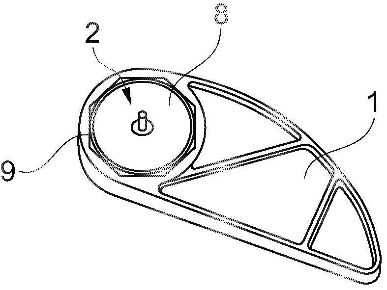
[0037] From figure 2 start from the icon, image 3 The other side of tensioning rail 1 is shown. The tensioning and damping unit 2 inserted into the recess 3 has a cover 7 which closes the housing 8 in a sealing manner on one side. cover 7 in Figure 5 and 6 It can be clearly seen in , while in image 3 In the middle, only the housing 8 and the spring 9 wound around the housing 8 on the outside are visible. The spring 9 is fixed in the slot 10, see for example Figure 7 . The ...


PUM


Abstract

The unit (2) has a housing (8) rotationally fixed to an internal combustion engine. A lid is attached relative to a clamping rail (1). The lid comprises a projection projected into interior part of the housing. The interior part of the housing is divided into a high pressure chamber and a reservoir chamber. An end of the lid is provided with a spring (9). A check valve is incorporated into the reservoir chamber. A pressure compensation element is provided in the reservoir chamber. The projection is sealed at an inner wall of the housing.

Description

technical field [0001] The invention relates to a tensioning and damping unit for a traction mechanism transmission of an internal combustion engine, the tensioning and damping unit having: a housing designed for mounting in a rotationally fixed manner relative to an internal combustion engine and for receiving a fluid; and a cover part, the cover part is designed to be mounted in a rotationally fixed manner relative to the tensioning rail. It is also possible for the housing to be mounted in a rotationally fixed manner relative to the tensioning rail, and for the cover to be mounted in a rotationally fixed manner relative to the internal combustion engine. Furthermore, tensioning and damping units are also referred to as tensioner and damper units. Background technique [0002] Such tensioning and damping units are used in motor vehicles, such as passenger cars (Pkw) or trucks (Lkw), but can also be used in traction gear drives of other land, air or water-related vehicles....

Claims


Application Information

Patent Timeline
Patent Type & Authority Patents(China)
IPC IPC(8): F02B67/06F16H7/08
CPCF16H7/0836F16H2007/081F16H2007/0859F16H2007/0893
Inventor 米夏埃尔·卡斯特纳尔
Owner SCHAEFFLER TECH AG & CO KG
Why Eureka
Try Eureka