
Address distribution method and system

An allocation method and address technology, which are applied in the field of address allocation method and system, and can solve the problem that the automatic allocation of business module addresses cannot be realized.

Active Publication Date: 2012-10-31
ZTE CORP
View PDF5 Cites 0 Cited by
  • Summary
  • Abstract
  • Description
  • Claims
  • Application Information

AI Technical Summary

Problems solved by technology

[0003] The present invention provides an address allocation method and system to at least solve the problem in the related art that the automatic allocation of the address of the service module in the optical network transmission entity cannot be realized

Method used


Image

  • Address distribution method and system
  • Address distribution method and system
  • Address distribution method and system

Examples


Embodiment Construction

[0034] Hereinafter, the present invention will be described in detail with reference to the drawings and examples. It should be noted that, in the case of no conflict, the embodiments in the present application and the features in the embodiments can be combined with each other.

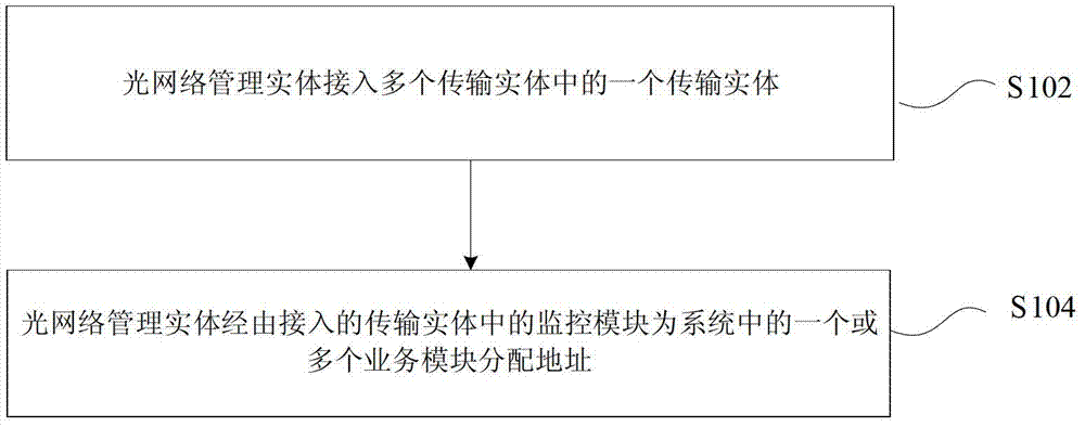
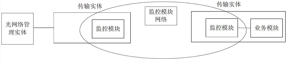
[0035] figure 1 is a flowchart of an address allocation method according to an embodiment of the present invention. Such as figure 1 As shown, the method can be applied to a system including an optical network management entity and one or more transmission entities, wherein each transmission entity includes: a monitoring module and one or more service modules corresponding to the monitoring module, which may include The following processing steps:

[0036] Step S102: the optical network management entity accesses one of the multiple transport entities;

[0037] Step S104: the optical network management entity assigns addresses to one or more service modules in the system via the monitoring module...


PUM


Abstract

The invention discloses an address distribution method and a system. The method is applied to a system including one optical network management entity and one or more than one transmission entity, wherein each transmission entity comprises a monitoring module, and more or more than one service module corresponding to the monitoring module; the optical network management entity accesses one of the transmission entities; and the address is distributed to the optical network management entity by the service module(s) in the transmission entity which the optical network management entity accesses. Due to the adoption of the technical scheme, through the cooperated operation and information interaction of the optical network management entity, the monitoring modules and the service modules, the address distribution to all ports of all service modules in the system is completed, and a function is laid for creating auto routing of the optical network.

Description

technical field [0001] The present invention relates to the communication field, in particular, to an address allocation method and system. Background technique [0002] At present, when using optical transmission equipment for service delivery, it is first necessary to plan the network, then perform optical fiber connection according to the network plan, and finally perform service configuration to complete service transmission. However, with the rapid development of optical network technology, the optical transmission network is becoming more and more complex, and the transmission distance is also increasing, which brings a great burden to network managers. The manual configuration method in the related art has been unable to catch up with the speed of network development, and is difficult to apply to large-scale network transmission. The automatic routing of the optical network introduced by this is more suitable for the development trend of optical network transmission....

Claims


Application Information

Patent Timeline
IPC IPC(8): H04L29/12H04B10/08
Inventor 赵丽娜邹红兵
Owner ZTE CORP
Learn More