Pipe cutting device for pipe cutter
A technology of cutting knives and pipe cutting machines, which is applied in the direction of pipe shearing devices, shearing devices, shearing machine equipment, etc., and can solve the problems of cutting knives wear and damage
Inactive Publication Date: 2012-11-21
ZHEJIANG TENGYUN REFRIGENRATION TECH
View PDF5 Cites 0 Cited by
- Summary
- Abstract
- Description
- Claims
- Application Information
AI Technical Summary
Problems solved by technology
[0004] For example, because the pipe is metal, the cutting knife will be worn and damaged after a period of use, so it is necessary to design a pipe cutting knife that is easy to replace the knife
Method used
View moreImage
Smart ImageViewing Examples

Examples
Embodiment
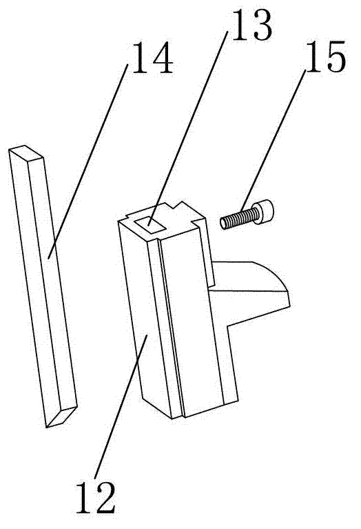
[0012] Example: such as figure 1 As shown, the pipe cutting knife of the present invention includes a knife seat 12, on the knife seat 12 is provided with a cutter mounting hole 13 that runs through the entire knife seat, a cutting tool 14 is set in the tool mounting hole 13, and a knife seat 12 is provided on the side wall There is a clamping screw 15 which abuts against the cutting tool 14 .
Login to view more PUM
 Abstract
The invention discloses a pipe cutting device for a pipe cutter, comprising a cutter holder, wherein a cutter mounting hole which passes through the whole cutter holder is arranged on the cutter holder; a cutting knife is arranged in the cutter mounting hole; a clamping screw is disposed on a side wall of the cutter holder; and the clamping screw is contacted with the cutting knife. According to the invention, the cutter mounting hole is arranged on the cutter holder; the cutting knife is arranged in the cutter mounting hole; the clamping screw is disposed on the side wall of the cutter holder; and a cutter is fixed in the cutter holder through the clamping screw; when the cutter needs to be replaced, the clamping screw is loosened, and after the cutter is replaced, the clamping screw is tightened, therefore, replacement of the cutter is very convenient.
Description
technical field [0001] The invention relates to a pipe cutting machine, in particular to a pipe cutting knife for the pipe cutting machine. Background technique [0002] The riser is an important part of the diffusion absorption refrigeration system. Before the riser is bent, a certain length must be reserved for clamping in order to facilitate the clamping of the tube. After the bend is completed, the excess part must be removed, and the bend The shape of the finished riser is quite special, it is difficult to cut by ordinary methods, and the inner pipe must not be damaged while cutting the outer pipe, such a cutting machine cannot be used for cutting, otherwise the inner and outer pipes will be cut together, The only thing that can be used is to slowly rotate the cutter in circles to cut, but the efficiency is too low and it is far from meeting the needs of processing. [0003] Therefore, it is very necessary to develop a pipe cutting machine that can automatically cut pi...
Claims
Login to view more Application Information
Patent Timeline
 IPC IPC(8): B23D21/10
Inventor 沈小毛杨永金蔡忠海
Owner ZHEJIANG TENGYUN REFRIGENRATION TECH
- R&D Engineer
- R&D Manager
- IP Professional
Why Eureka
- Industry Leading Data Capabilities
- Powerful AI technology
- Patent DNA Extraction
Try Eureka
Browse by: Latest US Patents, China's latest patents, Technical Efficacy Thesaurus, Application Domain, Technology Topic.
© 2024 PatSnap. All rights reserved.Legal|Privacy policy|Modern Slavery Act Transparency Statement|Sitemap