Rebound stopper
A technology of limiter and spring plate, which is applied in the direction of spring/shock absorber, spring, shock absorber, etc., can solve the problems of large impact sound and small compression (deformation), and achieve the effect of reducing impact sound
- Summary
- Abstract
- Description
- Claims
- Application Information
AI Technical Summary
Problems solved by technology
Method used
Image

Examples
Embodiment 1)
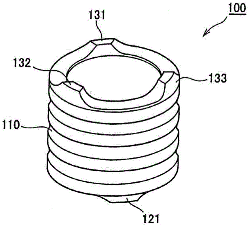
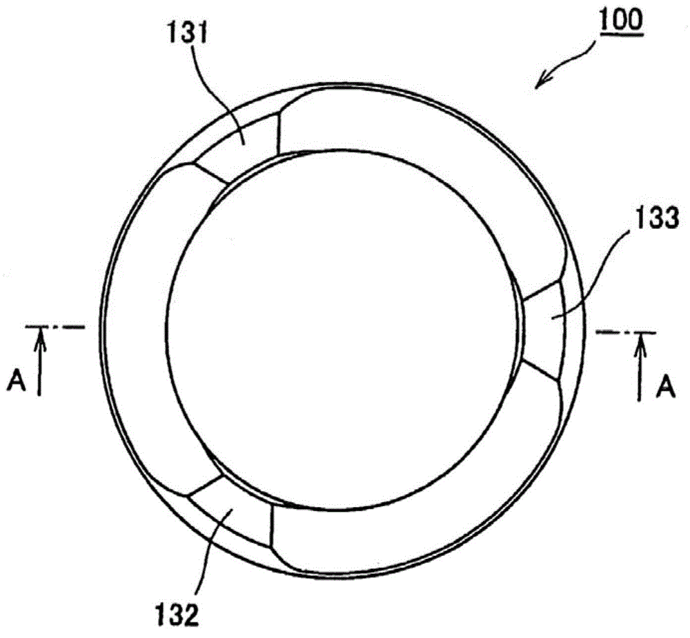
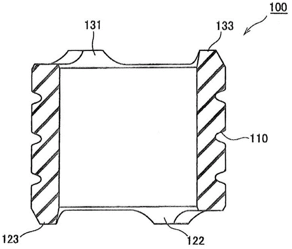
[0057] refer to Figure 1 to Figure 6 The rebound stopper in Embodiment 1 of the present invention will be described.
[0058]
[0059] refer to Figure 1 to Figure 4 The structure of the rebound stopper in Embodiment 1 of the present invention will be described.
[0060] The rebound stopper 100 of this embodiment is used for a suspension of an automobile or the like. That is, if Figure 4 As shown, the rebound limiter 100 is installed on the outer periphery of a rod (piston rod) 500 which is arranged in a cylinder 600 of the suspension and can reciprocate therein. In addition, the rebound stopper 100 has one end facing the rebound plate 510 provided on the rod 500 and the other end facing the rod guide 610 provided on the inner periphery of the cylinder 600 as a member to be impacted. In addition, the rod guide 610 functions as a bearing for the rod 500 .
[0061] In a normal state, one end of the rebound limiter 100 is in contact with the rebound plate 510 , and the o...
Embodiment 2)
[0078] refer to Figure 7 ~ Figure 11 A rebound stopper according to Embodiment 2 of the present invention will be described. Figure 7 is a perspective view of the rebound stopper of the present embodiment, Figure 8 ~ Figure 10 is a sectional view of the rebound stopper of this embodiment. Figure 11 It is a schematic sectional view showing the installation state of the rebound stopper of this embodiment. here, Figure 8 It is a cross-sectional view cut along the central axis of the rebound stopper and not passing through the through-hole 220 described later, corresponding to the Figure 9 Figure cut off at the BB position in . Figure 9 It is a sectional view cut along a position perpendicular to the central axis of the rebound stopper and passing through the through hole 220, which is equivalent to Figure 8 Figure cut off at the AA position in the middle. Figure 10 It is a cross-sectional view cut along the central axis of the rebound stopper and passing through th...
Embodiment 3)
[0091] Figure 12Example 3 of the present invention is shown. In the above-mentioned embodiment 2, the case where the through-holes are respectively arranged at the same position in the circumferential direction for each annular groove for any annular groove is shown, but in this embodiment, it is shown that a plurality of holes respectively provided in adjacent annular grooves. The through holes are arranged at positions shifted in the circumferential direction. Except for the arrangement positions of the through-holes, other structures and functions are the same as those of the second embodiment, so they will be briefly described.
[0092] In the rebound stopper 200a of this embodiment, a plurality of (four in this embodiment) annular grooves are formed at intervals in the direction in which the rod extends (that is, the axial direction) on the outer peripheral side thereof, and the overall The shape is a bellows tube shape. Hereinafter, these annular grooves are referred...
PUM
 Abstract
Description
Claims
Application Information
 - R&D
- Intellectual Property
- Life Sciences
- Materials
- Tech Scout
- Unparalleled Data Quality
- Higher Quality Content
- 60% Fewer Hallucinations
Browse by: Latest US Patents, China's latest patents, Technical Efficacy Thesaurus, Application Domain, Technology Topic, Popular Technical Reports.
© 2025 PatSnap. All rights reserved.Legal|Privacy policy|Modern Slavery Act Transparency Statement|Sitemap|About US| Contact US: help@patsnap.com