
Bottom lifting device for bracket

A technology for moving the frame and moving the frame, which is applied to the mine roof support, mining equipment, earthwork drilling and mining, etc. It can solve the problems that the bottom lifting mechanism cannot be installed, the frame is difficult to move, and the space of the support base is limited.

Active Publication Date: 2015-05-06
CATERPILLAR ZHENGZHOU
View PDF7 Cites 0 Cited by
  • Summary
  • Abstract
  • Description
  • Claims
  • Application Information

AI Technical Summary

Problems solved by technology

[0003] The technical problem to be solved by the present invention is to provide a bottom-lifting device for a bracket, which solves the problem in the prior art that a commonly used bottom-lifting mechanism cannot be installed due to the limited space of the base of the bracket and the requirement of a simple bottom-lifting structure, thus making it difficult to move the frame

Method used


Image

  • Bottom lifting device for bracket
  • Bottom lifting device for bracket
  • Bottom lifting device for bracket

Examples


Embodiment Construction

[0018] The bottom lifting device for the bracket provided by the present invention will be described below in conjunction with the embodiments and with reference to the accompanying drawings.

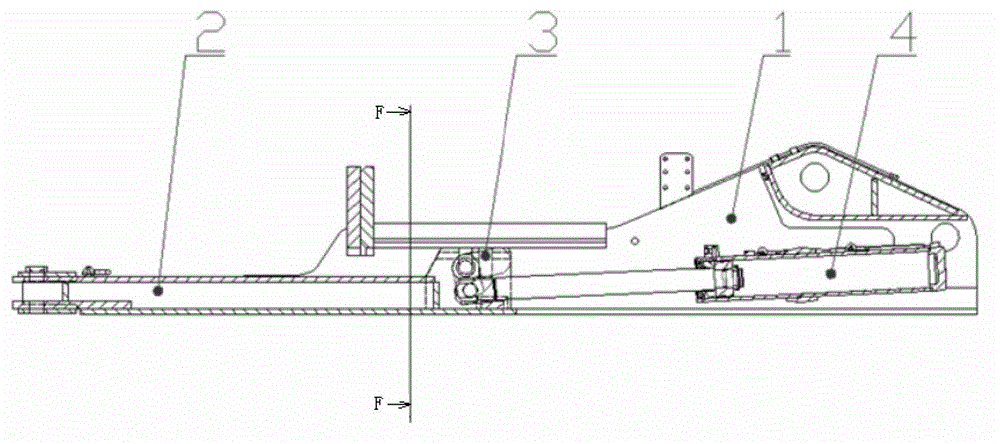
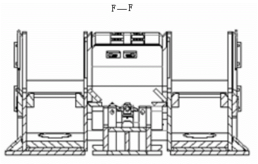
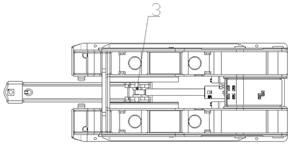
[0019] Such as Figure 1-Figure 7 As shown, the bottom lifting device for the support provided by the embodiment of the present invention includes a base 1 , a moving frame 2 , a rotating part 3 and a moving jack 4 . The rotating component 3 includes a first swing link 6 , a second swing link 7 and a connecting link 5 . Both ends of the connecting rod 5 are connected with the push frame 2, and the connection mode adopted in this embodiment is a movable connection, such as a hinge. The two swing rods are respectively connected to the connecting rod 5 , for example, by tailor welding, and the two connection points are the same point, that is, the two swing rods and the connecting rod 5 intersect at the same point. Of course, the rotating part 3 can also be integrally cast or forged, and...


PUM


Abstract

The invention discloses a bottom lifting device for a bracket. The bottom lifting device comprises a rotating component comprising a first swinging rod, a second swinging rod and a connecting rod, wherein both ends of the connecting rod are respectively connected with a thrusting frame of the bracket, so that the two swinging rods can rotate around the connecting rod as an axis; the two swinging rods are respectively connected with the connecting rod, and the first swinging rod is further movably connected with a thrusting jack of the bracket; and the second swinging rod is in contact with a base of the bracket in a bracket moving process. The bottom lifting device for the bracket, disclosed by the invention, is additionally provided with the rotating component used for lifting the bottom by improving the connection mode of the thrusting frame and the thrusting jack, so that when the bracket is in a bottom prone position state, the bottom lifting is realized under the actions of the second swinging rod of the rotating component and the base, the problems of bracket moving difficulty caused by the condition that the common bottom lifting mechanism cannot be installed due to the limited base space of the bracket and the requirement of simple structure of a bottom lifting structure in the prior art are solved.

Description

technical field [0001] The invention relates to a hydraulic support of a comprehensive mechanized coal mining face, in particular to a bottom lifting device for a hydraulic support. Background technique [0002] With the shortage of natural resources, it is required that coal seams under various complex geological conditions can be mined, but on the contrary, the design of hydraulic supports is required to be simpler. A hydraulic support is designed. The support is composed of top beam, cover beam, base, column, connecting rod, jack, etc. However, the coal seam is prone to soft bottom plate. Due to the limited space of the base and the simple structure required, it is impossible to install the commonly used The bottom lifting mechanism makes it difficult to move the frame. Contents of the invention [0003] The technical problem to be solved by the present invention is to provide a bottom-lifting device for a bracket, which solves the problem in the prior art that a commo...

Claims


Application Information

Patent Timeline
Patent Type & Authority Patents(China)
IPC IPC(8): E21D23/18
Inventor 夏亮王颖梁勇秦树振崔磊曹银苟付超王传奇曹从磊张芳卫何武宋治国
Owner CATERPILLAR ZHENGZHOU
Learn More