
Lag working face end top coal caving hydraulic support

A hydraulic support and working face technology, which is applied in mine roof supports, mining equipment, earthwork drilling and mining, etc., can solve problems such as poor safety protection facilities, difficulty in moving frames, and spontaneous combustion of leftover coal, so as to reduce the gangue content rate and solve the problem of moving Difficult to set up and high risk of exposure

Pending Publication Date: 2021-01-05
SHANXI SANYUAN COAL IND +2
View PDF0 Cites 0 Cited by
  • Summary
  • Abstract
  • Description
  • Claims
  • Application Information

AI Technical Summary

Problems solved by technology

Since the end of the working face is at the intersection of mining and transportation equipment, the equipment is densely arranged, and the surrounding rock at the end is under the action of various support pressures, the mine pressure is complicated, and the hydraulic support at the end is required for safety support. However, the existing The hydraulic support at the end of the hydraulic support has the problems of poor stability, poor safety protection facilities, and difficulty in moving the frame; if there is coal left on the roof, safety problems such as spontaneous combustion of the left coal are prone to occur in the goaf, so it is necessary to put the top coal at the end, and put the top coal on the top of the end. In the case of natural coal caving, because the end is suspended from the top and the pressure is lagging behind, the hydraulic support for caving coal at the end needs to be arranged with other supports on the lagging working face; when caving the top coal at the end of the lagging working face, there are supports close to the gob side The accumulated gangue falls into the transfer machine, causing the problem of high gangue content

Method used


Image

  • Lag working face end top coal caving hydraulic support
  • Lag working face end top coal caving hydraulic support
  • Lag working face end top coal caving hydraulic support

Examples


Embodiment Construction

[0018] In order to make the above objects, features and advantages of the present invention more obvious and understandable, the specific implementation manners of the present invention will be further described in detail below in conjunction with the accompanying drawings, but this does not constitute any limitation to the present invention.

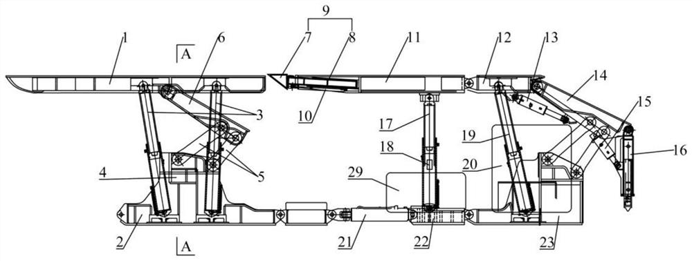
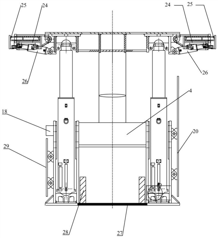
[0019] exist Figure 1 ~ Figure 4 Shown in the figure is a hydraulic support for top coal caving at the end of the present invention, which includes a split front frame and a rear frame. District orientation.

[0020] The front frame includes a first top beam 1 and a first base 2 . A first hydraulic prop 3 and a four-link structure are arranged between the first top beam 1 and the first base 2. The four-link structure is composed of an intermediate platform 4 of the front frame, two connecting rods 5 and a connecting beam 6. The intermediate platform 4. It is rigidly connected with the left and right bases of the front frame, and the ...


PUM


Abstract

The invention discloses a lag working face end top coal caving hydraulic support. The hydraulic support comprises a front frame and a rear frame which are split, wherein the front frame and the rear frame are connected through a pushing jack, a bottom protection steel plate is arranged between a left base and a right base of the front frame, a telescopic forepoling bar is arranged in a second topbeam of the rear frame and comprises a frame structure and a front tip, the second top beam and a third top beam of the rear frame and a second base and a third base are hinged through hinge pins, thedetachable hydraulic support can be additionally arranged, and a safety guard plate and a large-area gangue baffle are arranged on the third base of the rear frame. According to the hydraulic support, temporary supporting of a top plate can be achieved in the moving driving process, the empty top area in the moving driving process is reduced, and the advantages that the bottom heaving phenomenonis restrained, a support base is prevented from sinking, and the coal output gangue content is low are achieved.

Description

technical field [0001] The invention relates to the technical field of mine equipment, in particular to a hydraulic support for caving coal at the end of a lagging working face. Background technique [0002] The end top coal caving hydraulic support is an important equipment in the end top coal caving process of the working face, and it has the function of supporting the end top plate and the end top coal caving. Since the end of the working face is at the intersection of mining and transportation equipment, the equipment is densely arranged, and the surrounding rock at the end is under the action of various support pressures, the mine pressure is complicated, and the hydraulic support at the end is required for safety support. However, the existing The hydraulic support at the end of the hydraulic support has the problems of poor stability, poor safety protection facilities, and difficulty in moving the frame; if there is coal left on the roof, safety problems such as spont...

Claims


Application Information

Patent Timeline
Patent Type & Authority Applications(China)
IPC IPC(8): E21D23/04E21D23/03E21D23/20
CPCE21D23/0004E21D23/03E21D23/04E21D23/0409E21D23/0427E21D23/20
Inventor 张炳林赵宝友赵红星王海东王壮宿建军邵春瑞王建华栗东任红建孙超宋志强李广
Owner SHANXI SANYUAN COAL IND
Learn More