
A forward-moving hydraulic control lifting rack

A technology for lifting racks and racking devices, applied in the field of racking devices, can solve the problems of high labor intensity, low efficiency, and large safety hazards, and achieve the effects of improving labor efficiency, increasing safety factor, and reducing labor.

Active Publication Date: 2016-11-23
新汶矿业集团有限责任公司华丰煤矿
View PDF7 Cites 0 Cited by
  • Summary
  • Abstract
  • Description
  • Claims
  • Application Information

AI Technical Summary

Problems solved by technology

This kind of construction method requires personnel to stand under the empty roof for construction, which has great potential safety hazards, and manually erects the roof to the roof, which is labor-intensive and inefficient

Method used


Image

  • A forward-moving hydraulic control lifting rack
  • A forward-moving hydraulic control lifting rack
  • A forward-moving hydraulic control lifting rack

Examples


Embodiment Construction

[0015] The preferred embodiments of the present invention will be described in detail below in conjunction with the accompanying drawings, so that the advantages and features of the present invention can be more easily understood by those skilled in the art, so as to define the protection scope of the present invention more clearly.

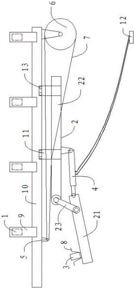
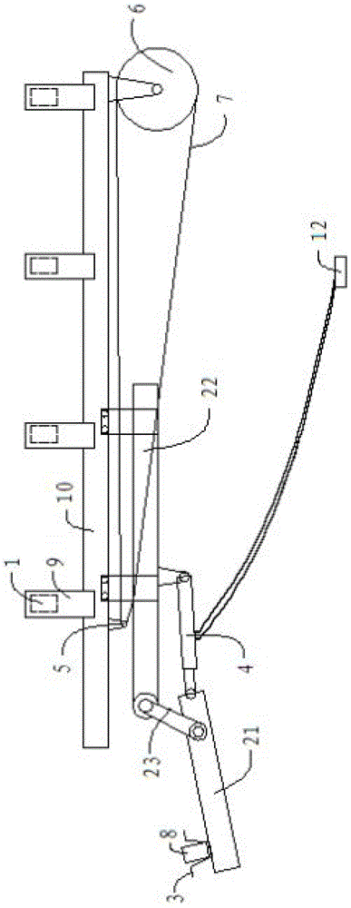
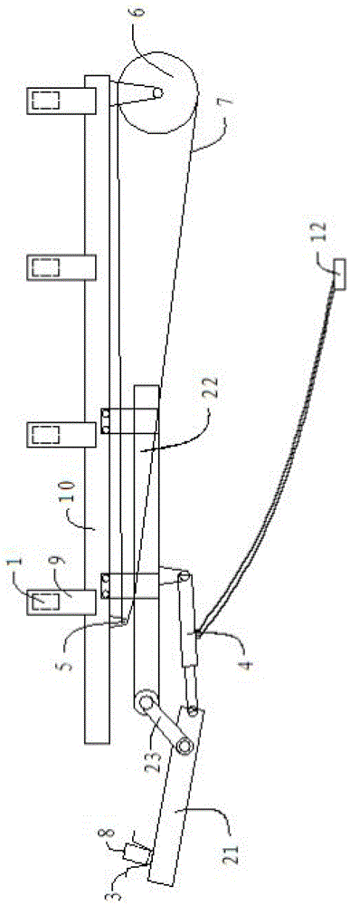
[0016] refer to figure 1 As shown, the forward-moving hydraulic control lifting frame shelving device of the present invention is installed under the first shed head 1 of fixed support, and it includes a front probe beam 2 for temporary support, and a front probe beam 2 There is a second shed head 3 on the top, which also includes an I-shaped steel runway 3 located between the first shed head 1 and the front probe beam 2, and the upper part of the I-beam runway 10 is fixedly connected with the first shed head 1. The lower part is slidably connected with the forward beam 2, wherein the forward beam 2 includes a first forward beam 21 and a second f...


PUM


Abstract

The invention discloses a front movement type hydraulic control lifting shed building device, and relates to the technical field of shed building devices in a shed building tunnel. The shed building device mainly solves the technical problems of the prior art that the safety hidden hazard is severe because a worker needs to stand just under the temporary shed head; the labor intensity is high and the efficiency is low when the shed head is built onto a top plate by the worker. The shed building device has the advantages that the action of an oil cylinder is controlled by a remote hydraulic valve, then the ascending and descending of a first front canopy are controlled, the shed head is lifted, the temporary support is realized, and the safety coefficient of the working environment of the worker under the safe and fixed first shed head is increased; the manual carrying of the shed head is changed into the hydraulic lifting of the shed head, so the labor intensity is decreased, and the labor efficiency is improved.

Description

technical field [0001] The invention relates to the technical field of scaffolding devices for scaffolding tunnels, in particular to a forward-moving hydraulically controlled lifting scaffolding device. Background technique [0002] The temporary support in the existing scaffolding roadway generally adopts manpower to dismantle the front beam first, then manually erects the U-shaped steel (shelf head) on the roof, and finally installs the front beam for temporary support. Such a construction method requires personnel to stand under the empty roof for construction, which has great potential safety hazards, and the roof is manually erected on the roof, which is labor-intensive and inefficient. Contents of the invention [0003] The present invention mainly solves the technical problems existing in the prior art, thereby providing a forward-moving liquid-controlled lifting frame shelving device with low labor intensity, convenient operation, safety and reliability. [0004] ...

Claims


Application Information

Patent Timeline
Patent Type & Authority Patents(China)
IPC IPC(8): E21D19/00
CPCE21D19/00
Inventor 王德田缪广文魏礼刚漆寒冬周长杰
Owner 新汶矿业集团有限责任公司华丰煤矿
Learn More