Exciting inrush current suppression apparatus

A technology of exciting inrush current and suppression devices, which is applied in the direction of circuit devices, emergency protection circuit devices, emergency protection circuit devices for limiting overcurrent/overvoltage, etc. Direct calculation of transformer core flux and other issues

Active Publication Date: 2013-02-06
KK TOSHIBA
View PDF6 Cites 8 Cited by
  • Summary
  • Abstract
  • Description
  • Claims
  • Application Information

AI Technical Summary

Problems solved by technology

[0008] In the method of suppressing inrush current using a circuit breaker with a resistance element, since it is necessary to add a circuit breaker with a resistance element to a normal circuit breaker, the size of the circuit breaker as a whole is increased
[0009] In addition, no matter which method suppresses the inrush current, it does not assume that the above-mentioned transformer that converts the three-phase AC voltage into a single-phase AC voltage is connected.
[0010] For example, i...

Method used


Image

  • Exciting inrush current suppression apparatus
  • Exciting inrush current suppression apparatus
  • Exciting inrush current suppression apparatus

Examples


no. 1 Embodiment approach

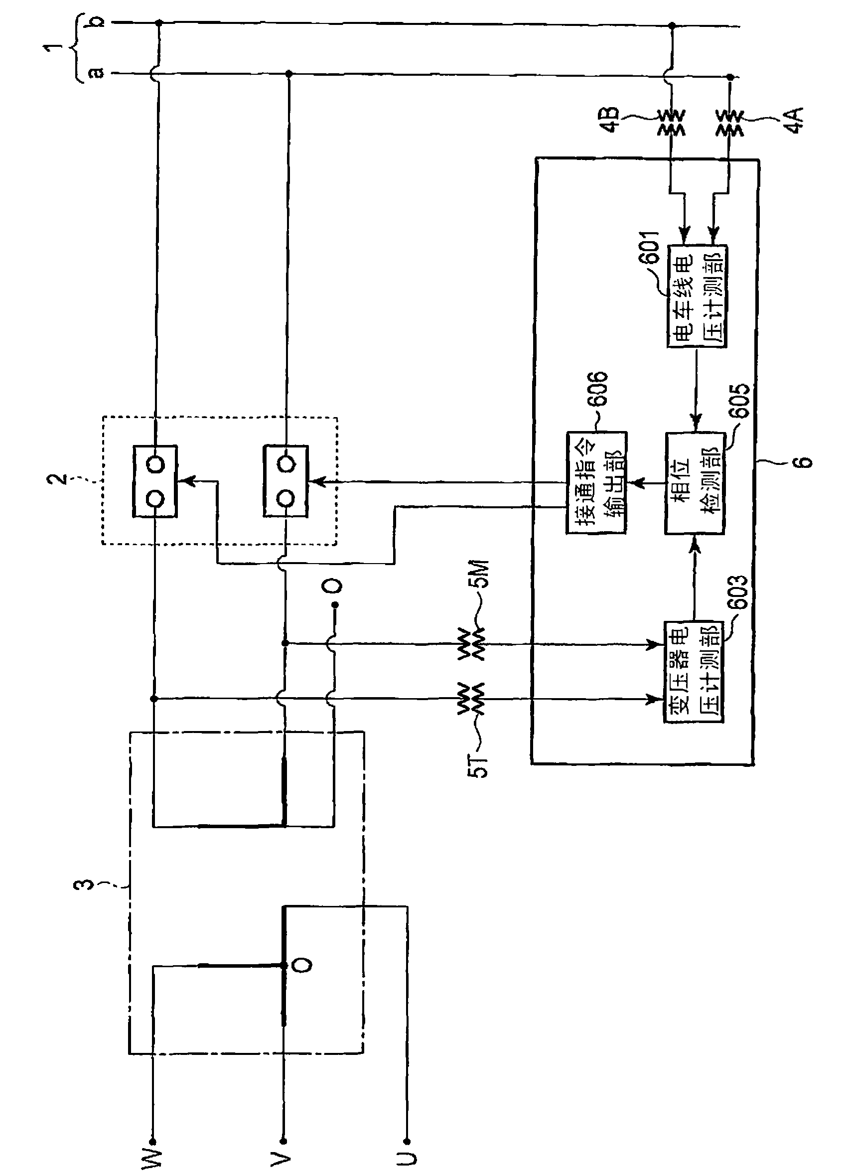
[0054] figure 1 It is a configuration diagram showing the configuration of a power system system using the magnetizing inrush current suppression device 6 according to the first embodiment of the present invention. In addition, the same reference numerals are assigned to the same parts in the subsequent drawings, and detailed description thereof will be omitted, and the different parts will be mainly described. In the following embodiments, repeated descriptions are similarly omitted.

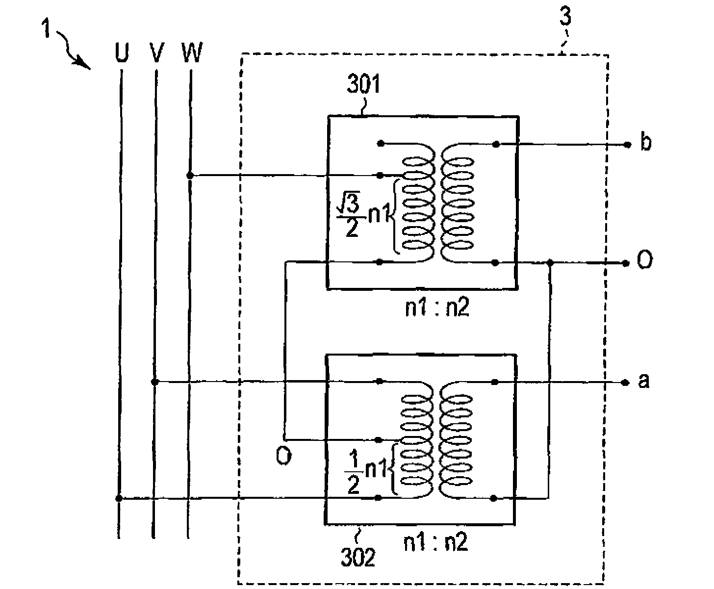
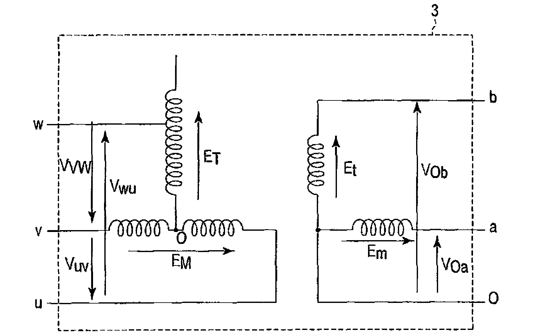
[0055] The power system system related to this embodiment includes a trolley line 1, a circuit breaker 2, a Scott connection transformer 3, two-phase trolley line voltage detectors 4A, 4B provided on the trolley line 1, and a Scott connection transformer. 3 on the secondary side (travel line 1 side) of the two-phase transformer secondary side voltage detectors 5M, 5T, and the excitation inrush current suppression device 6 .

[0056] The trolley line 1 is a single-phase AC power system compose...

no. 2 Embodiment approach

[0084] Figure 16 It is a configuration diagram showing the configuration of a power system system employing the field inrush current suppression device 6A according to the second embodiment of the present invention.

[0085] The power system system related to this embodiment is in figure 1 In the power system system according to the first embodiment shown, a magnetizing inrush current suppressing device 6A is provided instead of the magnetizing inrush current suppressing device 6 . The magnetizing inrush current suppression device 6A has a configuration in which, in the magnetizing inrush current suppression device 6 according to the first embodiment, the phase detection unit 605 is replaced by a phase detection unit 605A, and a steady magnetic flux calculation unit 602 and a residual magnetic flux calculation unit 604 are added. . Other structures are the same as those of the first embodiment.

[0086] refer to Figure 16 ~ Figure 18 , the structure of the excitation inr...

no. 3 Embodiment approach

[0101] Figure 22 It is a configuration diagram showing the configuration of a power system system employing a magnetizing inrush current suppression device 6B according to a third embodiment of the present invention.

[0102] The structure of the power system system related to this embodiment is that in Figure 16 In the shown power system system related to the second embodiment, the transformer primary side voltage detectors 5U, 5V, and 5W are installed instead of the transformer secondary side voltage detectors 5T, 5M, and the exciting inrush current suppressing device 6A is replaced by an exciting inrush current Suppression device 6B. The magnetizing inrush current suppression device 6B has a configuration in which the transformer voltage measurement unit 603 and the residual magnetic flux calculation unit 604 are replaced by the transformer voltage measurement unit 603B and the residual magnetic flux calculation unit 6A in the magnetizing inrush current suppression devic...


PUM


Abstract

An exciting inrush current suppression apparatus (6) for suppressing an exciting inrush current of a breaker (2) that opens/closes the connection of electric train lines (1) with a Scott connection voltage transformer (3). The exciting inrush current suppression apparatus (6) detects breakage phases when the connection of the voltage transformer (3) is broken. The exciting inrush current suppression apparatus (6) then measures the phase voltages of the phases of the electric train lines (1), and uses the detected breakage phases to turn on the breaker (2) on the basis of the measured phase voltages of the phases of the electric train lines (1).

Description

technical field [0001] Embodiments of the present invention relate to a magnetizing inrush suppressing device that suppresses a magnetizing inrush that occurs when a circuit breaker is turned on. Background technique [0002] In general, it is known that a large inrush current flows when a transformer core is excited with no load when the power is turned on in a state where there is residual magnetic flux. The magnitude of the inrush current is several times the rated load current of the transformer. If a large inrush current flows in this way, the system voltage fluctuates, and when this voltage fluctuation is large, it may affect the customer side. [0003] Therefore, as a method of suppressing the inrush current, there is known a method of using a circuit breaker with a resistance element in which an on-resistance is connected in series with the contacts. A circuit breaker with a resistive element is connected in parallel with the circuit breaker main contacts. The cir...

Claims


Application Information

Patent Timeline
IPC IPC(8): H01H33/59H01H9/54H01H9/56
CPCH01H33/593H01H9/563H02H9/002
Inventor 宇田川惠佑腰塚正丸山志郎斋藤实长山德幸
Owner KK TOSHIBA
Why Eureka
Try Eureka