Automatic calibration method for optical touch instrument

An automatic calibration and optical touch technology, applied in the input/output process of instruments, data processing, electrical digital data processing, etc., can solve the problems of light power failure, track disconnection, etc., and achieve the effect of solving the track disconnection phenomenon

Inactive Publication Date: 2013-02-13
ZHEJIANG NEW ZAILING TECH CO LTD
View PDF2 Cites 2 Cited by
  • Summary
  • Abstract
  • Description
  • Claims
  • Application Information

AI Technical Summary

Problems solved by technology

[0003] However, since the power of the light emitted by the optical sensor depletes with distance, especially in the middle of the active area, due to the error of the coordinate points of the optical sensors on the left and right sides, it is easy to have a disconnection of the trajectory, such as figure 1 As shown, the left optical sensor 1 and the right optical sensor 2 emit infrared rays, a light bar 4 is provided on the edge of the active area 3, and a glass area 5 is provided outside the light bar 4. In the active area 3, due to the activity The expansion of area 3, which is more prone to trajectory disconnection

Method used


Image

  • Automatic calibration method for optical touch instrument

Examples


Embodiment Construction

[0014] The present invention will be further described below in conjunction with the accompanying drawings and specific embodiments.

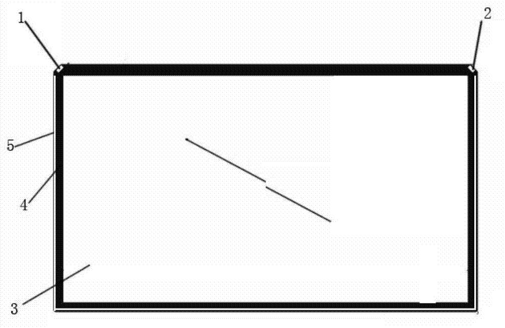
[0015] Such as figure 1 As shown, in the optical touch instrument, the left optical sensor 1 and the right optical sensor 2 emit infrared rays, and a light bar 4 is arranged on the edge of the active area 3, and a glass area 5 is arranged outside the light bar 4, and in the active area In 3, once a hand is touched, its left optical sensor 1 and right optical sensor 2 will respectively obtain a coordinate value, and then in the server, the coordinate value will be directly synthesized to obtain the final coordinate value, when the active area range When it is less, the track disjoint phenomenon is not obvious and cannot be recognized by the naked eye, so this defect can be ignored. However, when the active area increases, the contact track disjoint phenomenon also shows a tendency to enlarge. In general teaching or demonstration optical touch in...


PUM


Abstract

The invention discloses an automatic calibration method for an optical touch instrument. The method comprises the following steps: respectively acquiring contact coordinates (x1,y1) and (x2,y2) by virtue of optic sensors at the left and right sides; calculating weighted values (a, b) of the contact coordinates and the optical sensors at the left and right sides; and obtaining corrected coordinates (x3,y3) according to a formula of a*(x1,y1)+b*(x2,y2). Through respectively acquiring the contact coordinates by the optical sensors at the left and right sides, and then calibrating the coordinates of the point according to the weighted values at the left and right sides of the point, a smooth trace is obtained in an active region, and thus the trace disjointed phenomenon is solved.

Description

technical field [0001] The invention relates to an automatic calibration method for an optical touch instrument. Background technique [0002] The optical interactive touch screen creates a perfect interactive projection environment for users. It can not only project bright and clear images, but also has a unique interactive projection function, and can realize interactive functions on any surface, which is convenient for users to use. Optical The interactive touch device can realize interactive functions without an electronic whiteboard, and any flat wall or screen can become a touch screen for interactive projection, and can perform computer operations, drawing, writing, etc. on any screen projected by it. Internet access, etc., can be widely used in education and teaching, business meetings, product exhibitions, corporate culture promotion, corporate training, etc., which can make users' projections move as they wish. For example, the optical touch projector O-TOUCH laun...

Claims


Application Information

Patent Timeline
Patent Type & Authority Applications(China)
IPC IPC(8): G06F3/042
Inventor 许红林
Owner ZHEJIANG NEW ZAILING TECH CO LTD
Why Eureka
Try Eureka