Image processing apparatus, image processing method, and program

An image processing device and image technology, applied in image data processing, image communication, 3D image processing, etc., can solve problems such as inability to adjust parallax distribution

Inactive Publication Date: 2013-02-13
SONY CORP
View PDF2 Cites 28 Cited by
  • Summary
  • Abstract
  • Description
  • Claims
  • Application Information

AI Technical Summary

Problems solved by technology

However, since the range of the parallax distribution cannot be adjusted, an error may occur in which the entire image is shifted too much toward the viewer's side, or shifted too much toward the darker side as a result of the offset adjustment

Method used


Image

  • Image processing apparatus, image processing method, and program
  • Image processing apparatus, image processing method, and program
  • Image processing apparatus, image processing method, and program

Examples


no. 4 example )

[0075] 4. (Fourth embodiment) Processing example of determining virtual viewpoint positions with irregular intervals

[0076] 5. (Fifth Embodiment) Processing Example of Generating Virtual Viewpoint Images Using Shift Processing

[0077] 6. Configuration example of image processing device

[0078] 7. Summary of the configuration of the present disclosure

[0079][1. (First Embodiment) An embodiment in which determination processing of a virtual viewpoint position is performed according to image quality]

[0080] First, as a first embodiment of the image processing apparatus of the present disclosure, an embodiment in which determination processing of a virtual viewpoint position is performed according to image quality will be described.

[0081] [1-1. Overall processing sequence of processing executed by image processing apparatus]

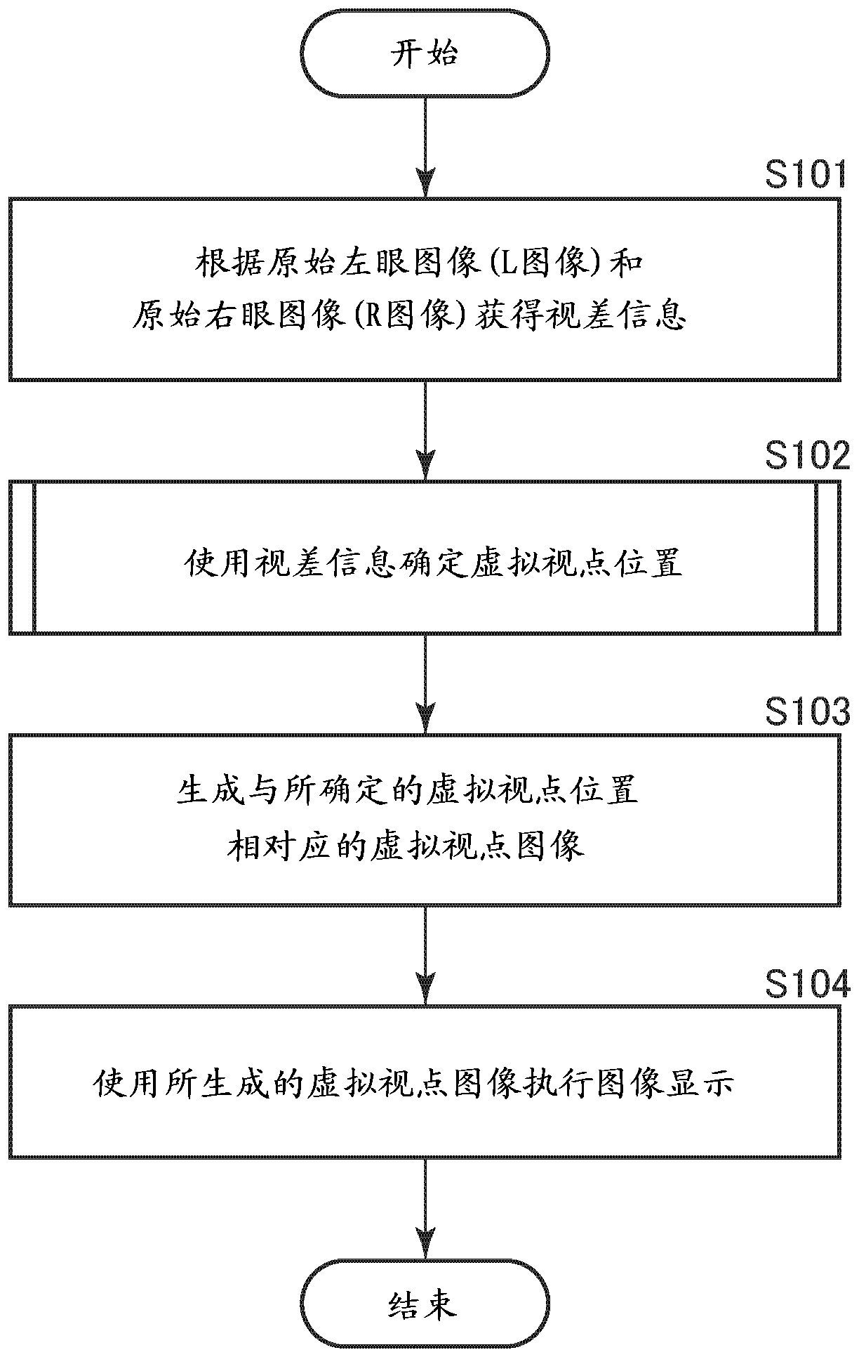
[0082] figure 1 is a flowchart illustrating the overall processing sequence of processing executed by the image processing apparatus accordin...

example 2

[0253] This processing example 2 is an example of determination processing of a virtual viewpoint position according to the following settings.

[0254] Total number of virtual viewpoints: N=9

[0255] Reference virtual viewpoint position number: Nfix=0

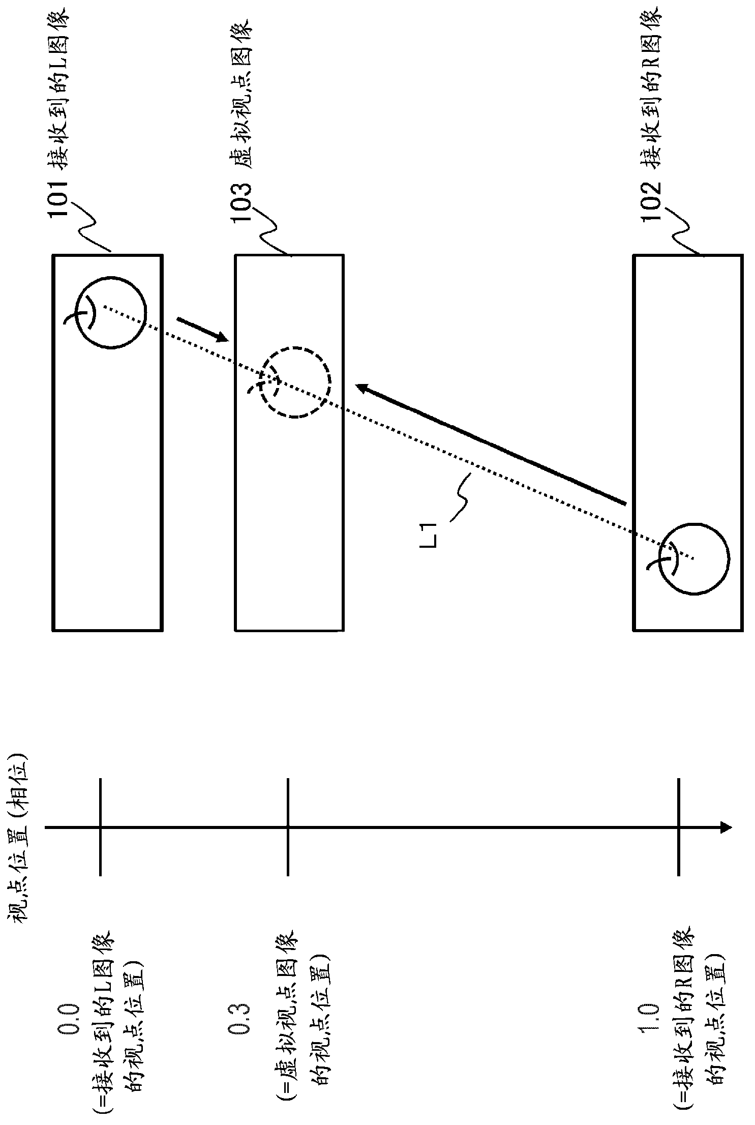
[0256] Reference virtual viewpoint position: Pfix=0.0 (received left eye image (L image) viewpoint position)

[0257] Virtual viewpoint interval: G=4 / 32,3 / 32,1 / 32,5 / 32

[0258] Figure 10 An example of virtual viewpoint position determination processing in the following four modes is shown.

[0259] (2a) N=9, Nfix=0, Pfix=0.0, G=4 / 32

[0260] (2b) N=9, Nfix=0, Pfix=0.0, G=3 / 32

[0261] (2c) N=9, Nfix=0, Pfix=0.0, G=1 / 32

[0262] (2d) N=9, Nfix=0, Pfix=0.0, G=5 / 32

[0263] This shows an example of the following: The nine thick lines shown in (2a) to (2d) are virtual viewpoint positions, at intervals of G [(2a) G=4 / 32, (2b) G=3 / 32, (2c) G=1 / 32, (2d) G=5 / 32] at regular intervals to set a total of nine (N=9) virtual viewp...

example 5

[0340] This processing example 5 is an example of determination processing of a virtual viewpoint position according to the following settings.

[0341] Total number of virtual viewpoints: N=9

[0342] Reference virtual viewpoint position number: Nfix=4

[0343] Reference virtual viewpoint position: Pfix=0.5 (the viewpoint position between the received left-eye image (L image) and the received right-eye image (R image))

[0344] Virtual viewpoint interval: G=4 / 32,3 / 32,1 / 32,5 / 32

[0345] Figure 13 An example of virtual viewpoint position determination processing in the following four modes is shown.

[0346] (5a) N=9, Nfix=4, Pfix=0.5, G=4 / 32

[0347] (5b) N=9, Nfix=4, Pfix=0.5, G=3 / 32

[0348] (5c) N=9, Nfix=4, Pfix=0.5, G=1 / 32

[0349] (5d) N=9, Nfix=4, Pfix=0.5, G=5 / 32

[0350] This shows an example of the following: the nine thick lines as shown in (5a) to (5d) are the virtual viewpoint positions at intervals of G [(5a) G=4 / 32, (5b) G=3 / 32, (5c) G=1 / 32, (5d) G=5 / 32...


PUM


Abstract

There is provided an image processing apparatus including a left eye image input unit configured to input a left eye image (L image) which is a left eye image signal applied to three-dimensional image display, a right eye image input unit configured to input a right eye image (R image) which is a right eye image signal applied to three-dimensional image display, a parallax information generating unit configured to generate parallax information from the left eye image (L image) and the right eye image (R image), and a virtual view point image generating unit configured to receive the left eye image (L image), the right eye image (R image), and the parallax information, and generate virtual view point images including a view point image other than view points of the received LR images.

Description

technical field [0001] The present disclosure relates to an image processing device, an image processing method, and a program, and more particularly, to an image processing device, an image processing method, and a program for generating a multi-viewpoint image applied to three-dimensional (3D) image display. Background technique [0002] Glasses-free type 3D display devices are already in use. The naked-eye type 3D display device allows a user to perceive a stereoscopic image without wearing glasses in a three-dimensional (3D) image display process. The glasses-free type 3D display device includes, for example, a lens plate or a parallax barrier on a display surface, which controls images entering left and right eyes according to viewing and listening positions. [0003] However, using this approach, correct stereoscopic views can only be obtained at limited viewing positions relative to the display. Therefore, when the user's viewing position is located at a position di...

Claims


Application Information

Patent Timeline
Patent Type & Authority Applications(China)
IPC IPC(8): H04N13/00
CPCH04N13/02H04N13/0011H04N13/0022H04N13/0404H04N13/0447G06T15/00H04N13/0409H04N13/305H04N13/111H04N13/128H04N13/31H04N13/351
Inventor 牛木卓绪形昌美
Owner SONY CORP
Why Eureka
Try Eureka