
A method and system for terminal triggering

A terminal and trigger message technology, applied in electrical components, wireless communication, network data management, etc., can solve the problems that the terminal cannot establish a connection with the server, cannot trigger the message to be sent to the terminal, and achieve the effect of real-time reporting

Active Publication Date: 2017-11-28
江苏慧煦电子科技有限公司
View PDF2 Cites 0 Cited by
  • Summary
  • Abstract
  • Description
  • Claims
  • Application Information

AI Technical Summary

Problems solved by technology

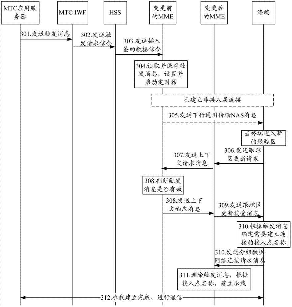
[0007] However, in the existing solutions, after the terminal moves while the terminal is in an idle state, the mobility management unit MME or SGSN will change accordingly, and the trigger message will still be stored in the mobility management unit before the change. In this way, the network may not be able to The trigger message is sent to the terminal, causing the terminal to fail to establish a connection with the server in time for data reporting

Method used


Image

  • A method and system for terminal triggering
  • A method and system for terminal triggering
  • A method and system for terminal triggering

Examples


Embodiment Construction

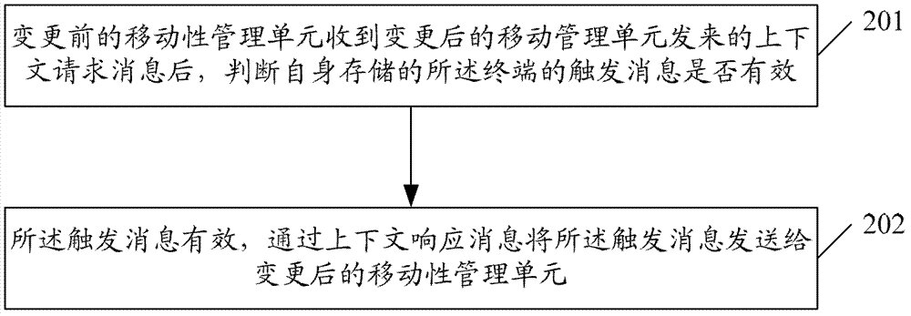
[0039] The basic idea of ​​the present invention is: after the mobility management unit before the terminal change receives the context request message sent by the changed mobility management unit, it judges whether the trigger message of the terminal stored by itself is valid; the trigger message is valid , the trigger message is sent to the changed mobility management unit through a context response message, and the changed mobility management unit sends the trigger message to the terminal.

[0040] In order to make the object, technical solution and advantages of the present invention clearer, the present invention will be further described in detail by citing the following embodiments and referring to the accompanying drawings.

[0041] figure 2 It shows the implementation process of the method triggered by the terminal of the present invention, as shown in figure 2 As shown, the method includes the following steps:

[0042] Step 201, after the mobility management unit...


PUM


Abstract

Disclosed is a method for triggering a terminal, comprising: a mobility management entity before change of a terminal determining whether a trigger message stored in itself is valid upon receiving a context request message sent by a mobility management entity after the change; if valid, sending the trigger message to the mobility management entity after the change through a context response message, and the mobility management entity after the change sending the trigger message to the terminal. Also disclosed is a system for triggering a terminal. According to the present invention, after movement of a terminal, a trigger message can still be sent to the terminal in time, thereby achieving real-time reporting of data.

Description

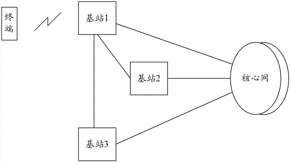
technical field [0001] The present invention relates to the field of machine type communication (Machine Type Communication, MTC) terminal management, in particular to a method and system for terminal triggering. Background technique [0002] The cellular wireless communication system is mainly composed of a core network (Core Network, CN), an access network (Radio AccessNetwork, RAN) and terminals. Among them, the core network is responsible for non-access layer affairs, such as terminal location update, and the core network is the user The anchor point of the plane; the access network includes the base station, or the base station and the base station control, and the access network is responsible for the access layer affairs such as wireless resource management, etc., and there may be physical or logical connections between the base stations according to the actual situation, such as figure 1 The connection between base station 1 and base station 2 or base station 3, and ...

Claims


Application Information

Patent Timeline
Patent Type & Authority Patents(China)
IPC IPC(8): H04W8/04H04W64/00
CPCH04W8/04H04W68/00
Inventor 吴昊
Owner 江苏慧煦电子科技有限公司
Learn More