Input device and manufacturing method thereof

A technology of an input device and a manufacturing method, applied in the input/output process of data processing, instruments, electrical digital data processing, etc., can solve the problem of high cost and achieve the effect of low cost

Inactive Publication Date: 2015-12-02
ALPS ALPINE CO LTD
View PDF6 Cites 0 Cited by
  • Summary
  • Abstract
  • Description
  • Claims
  • Application Information

AI Technical Summary

Problems solved by technology

Therefore, causing the cost to further increase

Method used


Image

  • Input device and manufacturing method thereof
  • Input device and manufacturing method thereof
  • Input device and manufacturing method thereof

Examples


Embodiment Construction

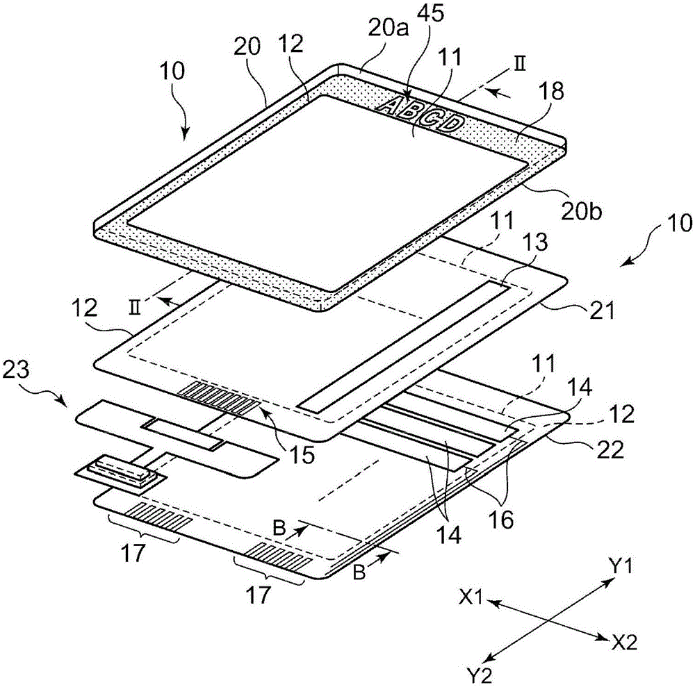
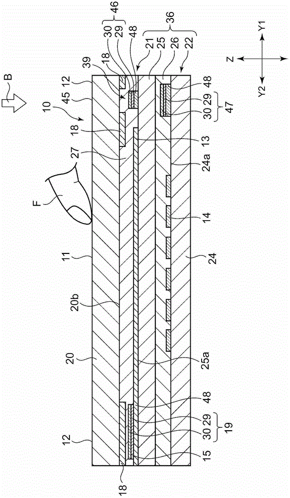
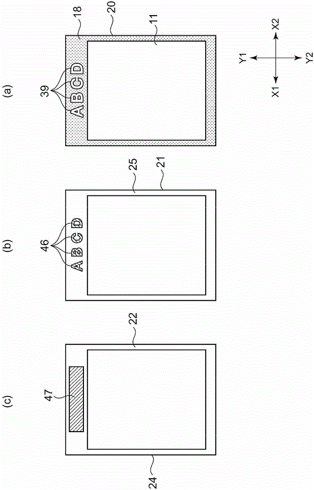
[0114] figure 1 is an exploded perspective view of the input device of this embodiment, figure 2 will be figure 1 The shown input device is formed in an assembled state and is cut along the line II-II and is a partially enlarged longitudinal sectional view viewed from the direction of the arrow, image 3 (a) is a plan view of the surface panel in the first embodiment, image 3 (b) is a plan view of the upper substrate in the first embodiment, image 3 (c) is a plan view of the lower substrate in the first embodiment, Figure 4 will be image 3 An enlarged plan view of the logo part (display part) appearing at the decorative position of the surface panel after the surface panel, upper substrate, and lower substrate shown are assembled, Figure 5 will be image 3 The enlarged plan view of the logo part (display part) that appears at the decorative position of the surface panel after the surface panel, upper substrate, and lower substrate are assembled is the same as F...


PUM


Abstract

The invention aims to provide an input device that enables, with lower manufacture cost, a display portion to be mounted on a decorative layer. The input device (10) is characterized in that a surface panel (20), a decorative layer (18) and transparent base materials (24, 25) are laminated together. The input device (10) comprises: the transparent base materials (24, 25), transparent electrode layers (13, 14) formed at a position opposite to an input area (11), and a sensor portion (36) formed by metal wiring layers (16, 19) at a position opposite to the decorative layer (18). The decorative layer (18) is provided with a display window (39) that allows light to pass. A surface side of the transparent base materials opposite to the display window (39), equal to a surface side with the metal wiring layers, is equipped with display metal layers (46, 47) of metal material layers, and the display metal layers are identical with the metal wiring layers, thus forming a display poriton (45) that allows the display metal layers to be observed via the display window (39) when a user is overlooking.

Description

technical field [0001] The present invention relates to an input device that is mounted on a portable device or other electronic device and is operated by bringing an operating body such as a finger into contact with an operation panel. Background technique [0002] Figure 17 (a) is a top view of a conventional input device (touch panel), Figure 17 (b) is to Figure 17 The input device shown in (a) is cut along the A-A line in the thickness direction and is observed from the longitudinal sectional view of the arrow direction, Figure 17 (c) is a longitudinal cross-sectional view in which the marking portion is three-dimensionally displayed. [0003] Figure 17 The shown input device 1 has: a surface panel 2 formed of glass or the like; a sensor portion 3; an optically transparent adhesive layer (OCA) 4 for joining the surface panel 2 and the sensor portion 3; Decorative layer6. [0004] Such as Figure 17 As shown in (b), the decorative layer 6 is formed on the back surfa...

Claims


Application Information

Patent Timeline
Patent Type & Authority Patents(China)
IPC IPC(8): G06F3/041
Inventor 渡边武浅部喜幸堀野武信井上靖稔
Owner ALPS ALPINE CO LTD
Why Eureka
Try Eureka