Light source device, image display device and television receiver device
A light source device and light source technology, applied in installation, optics, connection components, etc., can solve the problems of high calorific value, shortened life of light-emitting diodes, low light output and low current, and achieve temperature rise suppression, simple maintenance, position change, and increase The effect of a large contact area
- Summary
- Abstract
- Description
- Claims
- Application Information
AI Technical Summary
Problems solved by technology
Method used
Image

Examples
Embodiment approach 1-1
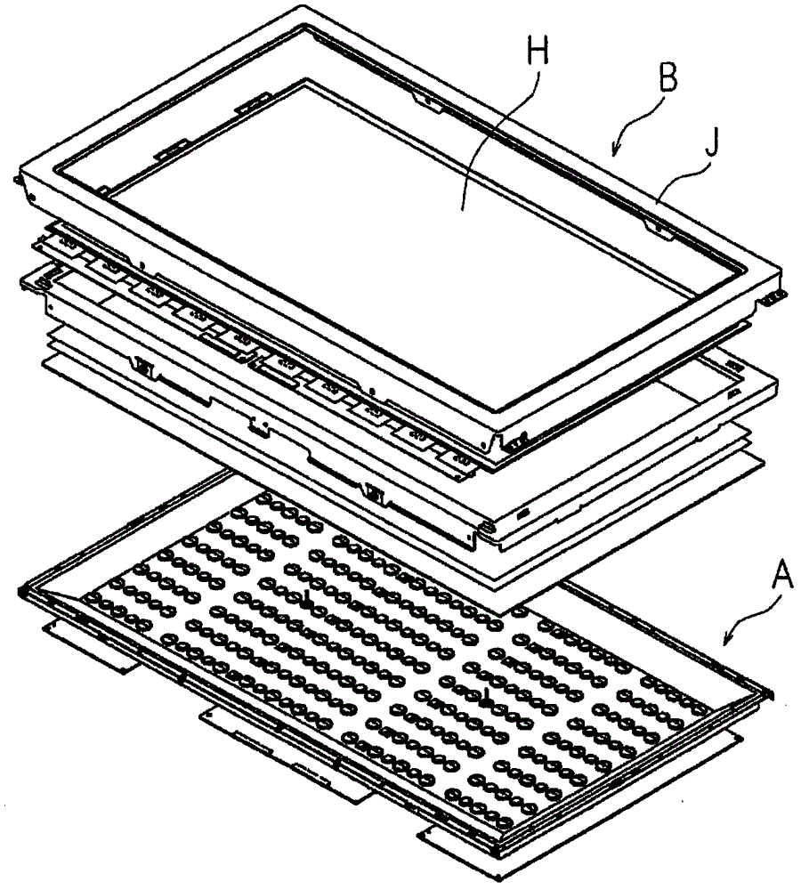
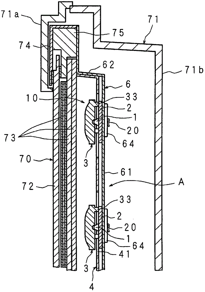
[0137] image 3 Is a cross-sectional view showing the structure of an image display device including a light source device according to Embodiment 1-1 of the present invention, Figure 4 It is a schematic perspective view of a part of the light source device decomposed, Figure 5 It is a perspective view showing the structure of the light source unit of the light source device of the image display device according to Embodiment 1-1 of the present invention.
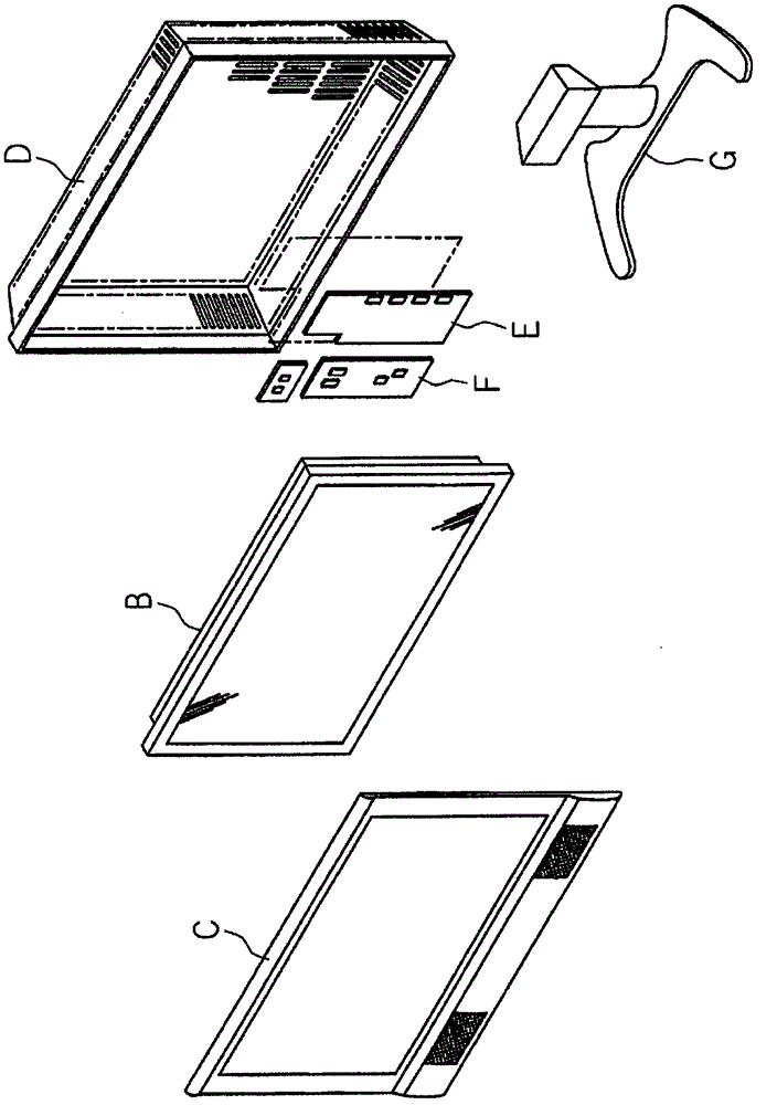
[0138] The image display device 1 of the present invention includes: a display portion 70 (liquid crystal panel H) having a display surface for displaying images on the front side; and a light source device A (backlight device), the light source device A including the display portion The light source unit 10 on the rear side of 70; and a housing 71 (C, D) that covers the periphery of the display portion 70 and the rear side of the light source device A.
[0139] The display unit 70 includes: a display panel 72 having a display ...
Embodiment approach 1-2
[0168] Picture 10 It is a cross-sectional view of a main part showing a state in which the light source unit 10 is held by the holder 6 in the image display device of the embodiment 1-2.
[0169] On the other surface 2b of the light emitting diode substrate 2, a plurality of locking portions 20, 20,... 20 for holding the light source unit 10 to the holder 6 are provided at a plurality of locations. The locking portion 20 is made of metal and can be elastically deformed. The locking portion 20 is obtained by bending a plate material. For example, the elongated plate material is bent symmetrically with respect to the center in the longitudinal direction, and the short side direction is fixed to the other surface 2 b along the longitudinal direction of the light emitting diode substrate 2.
[0170] That is, the locking portion 20 is composed of a base 20c and a pair of crimping pieces 20d, 20d, wherein the base 20c is the center portion in the longitudinal direction of the locking p...
Embodiment approach 1-3
[0178] Picture 11 It is a cross-sectional view of a main part showing a state in which the light source unit 10 is held by the holder 6 in the image display device according to Embodiment 1-3 of the present invention.
[0179] On the other surface 2b of the light emitting diode substrate 2, a plurality of locking portions 20, 20,... 20 for holding the light source unit 10 to the holder 6 are provided at a plurality of locations. The locking portion 20 is made of metal and can be elastically deformed. The locking portion 20 is obtained by bending a plate material. For example, a long-shaped plate material is bent symmetrically with respect to the center of the long side direction, and the short side direction is fixed to the other surface 2b along the long side direction of the light emitting diode substrate 2.
[0180] Specifically, the locking portion 20 is composed of a flat base 20f, a pair of crimping pieces 20g and 20g, and anti-detachment portions 20h, 20h, wherein the base...
PUM
| Property | Measurement | Unit |
|---|---|---|
| thickness | aaaaa | aaaaa |
| thickness | aaaaa | aaaaa |
Abstract
Description
Claims
Application Information