
Fast distance protection for energy supply networks

A multi-phase power supply and protection equipment technology, applied in the direction of automatic disconnection emergency protection device, emergency protection circuit device, emergency protection data processing device, etc., can solve problems such as delay, and achieve the effect of preventing the danger of wrong judgment

Inactive Publication Date: 2013-03-20
SIEMENS AG
View PDF6 Cites 15 Cited by
  • Summary
  • Abstract
  • Description
  • Claims
  • Application Information

AI Technical Summary

Problems solved by technology

[0006] The two described methods have the disadvantage that, depending on the size of the measurement window used, a minimum number of sampled values ​​is required for the calculation of complex current and voltage values, so that a decision about the presence of a short circuit on a wire can only be made with a certain delay out

Method used


Image

  • Fast distance protection for energy supply networks
  • Fast distance protection for energy supply networks
  • Fast distance protection for energy supply networks

Examples


Embodiment Construction

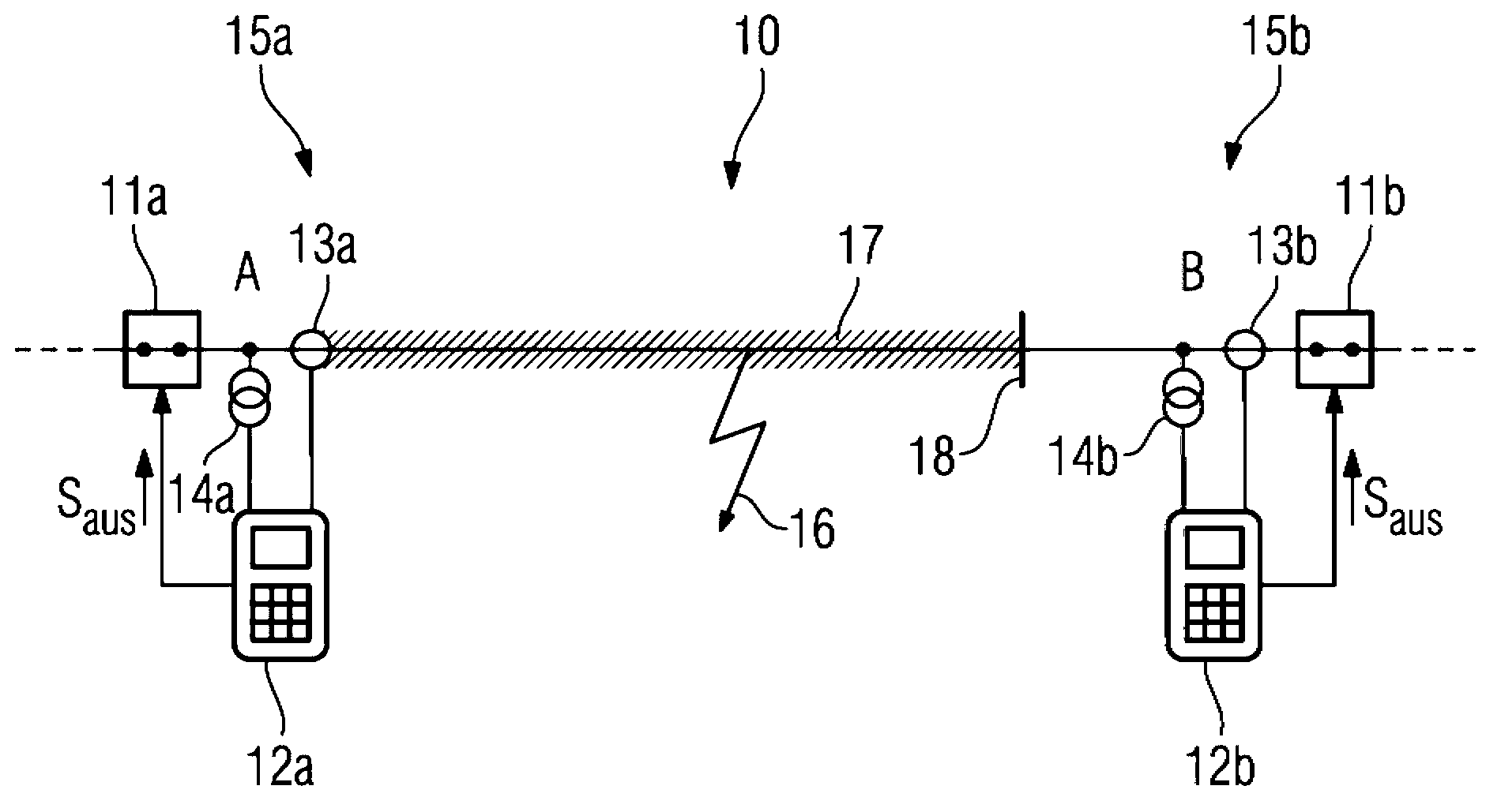
[0090] figure 1 Lines 10 of a polyphase power supply network not shown in detail otherwise are shown. The conductor 10 is delimited at its two ends A and B by power switches 11a and 11b via which in the event of a fault the relevant phase conductor of the conductor 10 can be disconnected. For this purpose, protective devices 12a and 12b are provided at the conductor ends A and B at measuring points 15a and 15b. The current and voltage signals recorded at the respective measuring points 15a, 15b by means of the only schematically indicated current transformers 13a, 13b and voltage transformers 14a, 14b are transmitted to the protective devices 12a and 12b.

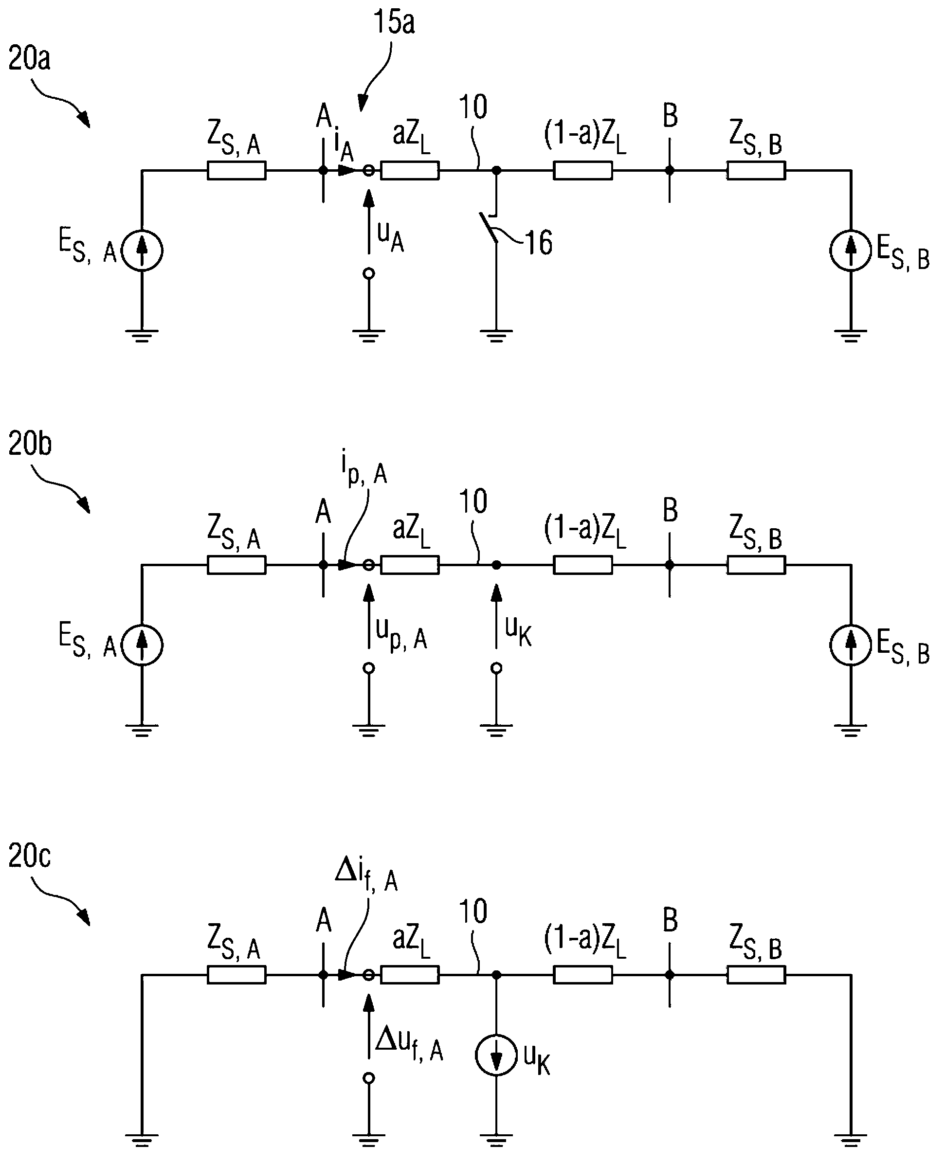
[0091] The protective devices 12 a , 12 b sample the current and voltage signals by means of A / D conversion and carry out a fault analysis of the current and voltage sampled values ​​thus produced in order to be able to detect a possible short circuit 16 on the line 10 . Such a short circuit 16 can either be a single-phas...


PUM


Abstract

The invention relates to a method for detecting a short circuit (16) on a line (10) of a multi-phase electrical energy supply network, in which current and voltage sampled values are recorded and a fault signal is generated if a fault evaluation performed by an electrical protection device (12a) indicates a short circuit (16) present on the line (10). In order to generate a fault signal even more quickly than before, in particular for clear faults, instantaneous reference voltage values are calculated from instantaneous current and voltage sampled values recorded before the occurrence of the short circuit (16), and instantaneous comparative voltage values are calculated from instantaneous current and voltage sampled values recorded before the occurrence of the short circuit (16) and instantaneous current and voltage sampled values recorded during the short circuit (16). Then a rectified reference voltage value is calculated from consecutive instantaneous reference voltage values, and a rectified comparative voltage value is calculated from consecutive instantaneous comparative voltage values. The fault signal is generated if the difference of the rectified comparative voltage value and the rectified reference voltage value exceeds a triggering threshold value. The invention further relates to a corresponding electrical protection device (12a).

Description

technical field [0001] The invention relates to a method for detecting a short circuit on a conductor of a polyphase power supply network with a grounded neutral point, in which current and voltage sampled values ​​at a measurement location at one end of the conductor to be monitored are recorded by an electrical protective device, And if a fault analysis of the current and voltage sampled values ​​by the electrical protection device reveals that there is a short circuit on the conductor, a first fault signal indicating a short circuit on the conductor is generated. The invention also relates to a correspondingly constructed electrical protective device. Background technique [0002] In a power supply network with a grounded center point, it must be possible to disconnect a faulty conductor particularly quickly in the event of a clear short circuit. Due to the high short-circuit power, short-circuits in such supply networks are particularly dangerous because they place high...

Claims


Application Information

Patent Timeline
IPC IPC(8): G01R31/02G01R31/08H02H3/40H02H3/44H02H7/26
CPCH02H7/26G01R31/025G01R31/085H02H1/0092G01R31/52
Inventor J.布鲁姆谢恩C.德茨尼斯M.科瑞特
Owner SIEMENS AG
Learn More