Brake control apparatus
A brake control and brake fluid technology, which is applied in the direction of control devices, brake control systems, brake transmission devices, etc., can solve the problems that the driver is difficult to provide a sense of brake operation, and it is difficult to control the pressure of the wheel cylinder arbitrarily.
- Summary
- Abstract
- Description
- Claims
- Application Information
AI Technical Summary
Problems solved by technology
Method used
Image

Examples
Embodiment 1
[0080] First, the configuration will be described.
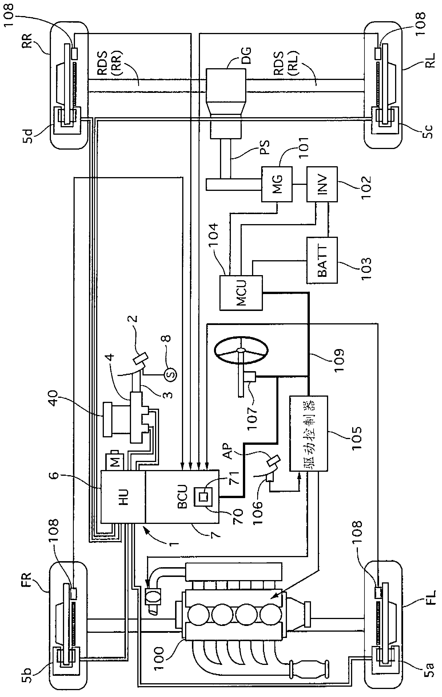
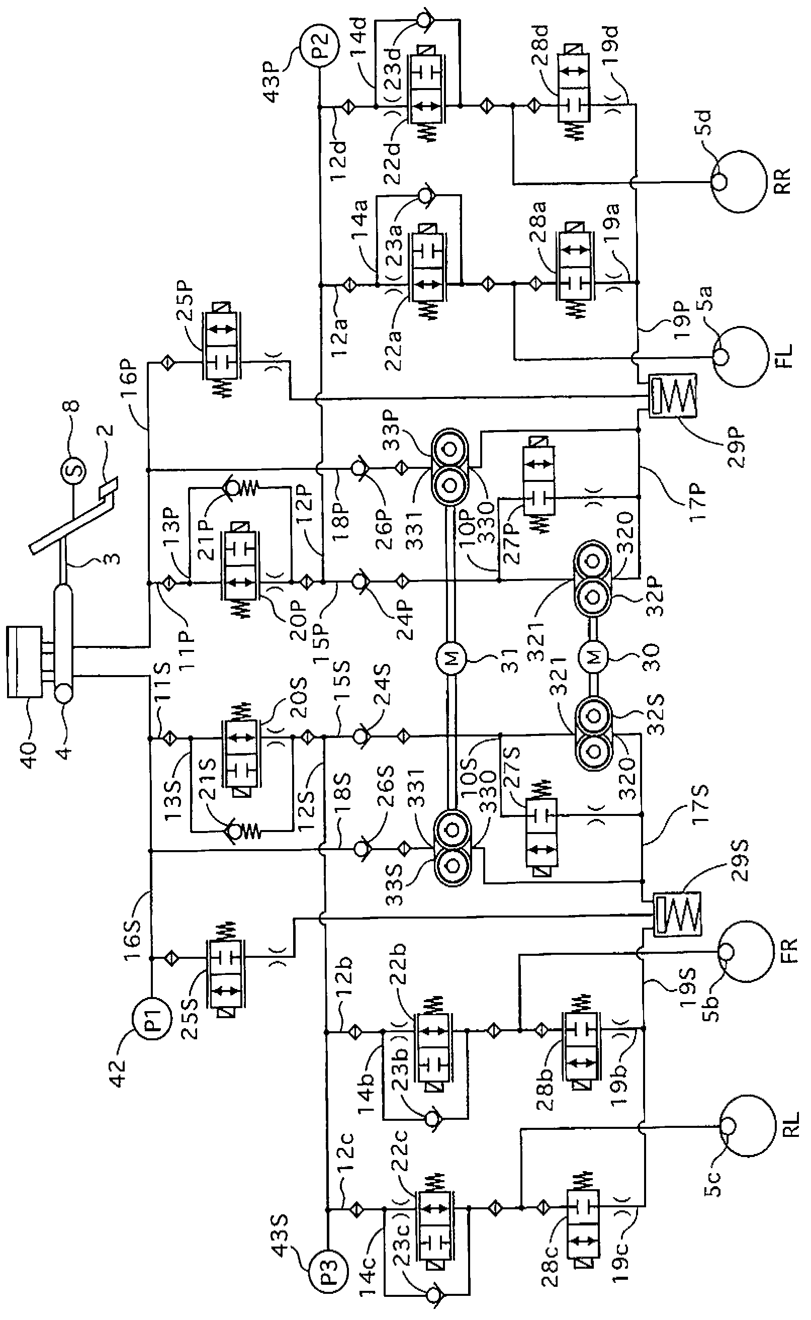
[0081] figure 1 is a system configuration diagram showing a braking and driving system of a vehicle to which the braking control device 1 of the first embodiment is applied, figure 2 It is a circuit configuration diagram of the brake control device 1 of the first embodiment. The vehicle is a hybrid vehicle in which front wheels FL, FR are driven by an internal combustion engine (engine 100 ), and rear wheels RL, RR are driven by an electric motor (motor generator 101 ). Each wheel FL, FR, RL, RR is provided with a wheel speed detection device (wheel speed sensor) 108 that detects its rotational speed (wheel speed). It should be noted that each electronic control unit (control unit 7 , motor control unit 104 , drive controller 105 ) is connected to each other through a signal line (CAN communication line 109 ) capable of information exchange. The drive system of the vehicle has an engine 100 , a motor generator 101 , an i...
Embodiment 2
[0220] The brake control device 1 of the second embodiment differs from the device 1 of the first embodiment in that only one of the two systems (P system, S system) of the piping structure of the hydraulic control unit 6, for example, the S system, An inflow gate valve 25, a return device (second pump 33) and a return circuit (pipeline 18) are provided.
[0221] First, the configuration will be described.
[0222] Figure 44 It is a circuit configuration diagram of the hydraulic control unit 6 of the device 1 of the second embodiment. The constitution of S system and embodiment 1 ( figure 2 )same. As far as the P system is concerned, the pipeline 18 and the second pump 33 are not provided. The second motor 31 drives only the second pump 33S of the S system. There is no inflow gate valve 25 on the third brake circuit (line 16 ) of the P system, and a check valve 290 as a pressure regulating valve is integrally provided on the oil storage chamber 29P of the P system. Tha...
Embodiment 3
[0230] The difference between the brake control device 1 of Embodiment 3 and the device 1 of Embodiment 1 is that, as the return device of the hydraulic control unit 6 , the second pump 33 is not provided on the return circuit (pipeline 18 ), but the second pump 33 is used. A pump 32 works as a return device.
[0231] First, the configuration will be described.
[0232] Figure 45 It is a circuit configuration diagram of the hydraulic control unit 6 of the device 1 of the third embodiment. and figure 2 Differently, the pipeline 18 and the second pump 33 are not provided in the P system and the S system. In addition, in the first brake circuit, on the pipelines 12P and 12S before branching into the pipelines 12a, 12d, 12b, and 12c corresponding to each wheel, there are respectively provided second switching valves that are normally open electromagnetic valves. 41P, 41S. At the connection point of the pipeline 11 and the pipeline 12 , a hydraulic pressure sensor 44 for det...
PUM
 Abstract
Description
Claims
Application Information
 - R&D
- Intellectual Property
- Life Sciences
- Materials
- Tech Scout
- Unparalleled Data Quality
- Higher Quality Content
- 60% Fewer Hallucinations
Browse by: Latest US Patents, China's latest patents, Technical Efficacy Thesaurus, Application Domain, Technology Topic, Popular Technical Reports.
© 2025 PatSnap. All rights reserved.Legal|Privacy policy|Modern Slavery Act Transparency Statement|Sitemap|About US| Contact US: help@patsnap.com