Elastic pressure relief system for reducing breaker operation work

A technology of operating power and circuit breaker, applied in the direction of high-voltage air circuit breaker, circuit, high-voltage/high-current switch, etc., can solve the problem of reducing the opening speed to zero, reducing the operating power of the circuit breaker, and hindering the opening movement of the circuit breaker.

Active Publication Date: 2013-03-27
YIHE ELECTRIC GRP
View PDF5 Cites 2 Cited by
  • Summary
  • Abstract
  • Description
  • Claims
  • Application Information

AI Technical Summary

Problems solved by technology

However, as the gas in the compression chamber is continuously compressed and the arc combustion energy continues to increase, it becomes inevitable that the gas pressure in the compression chamber continues to rise. When the pressure of the compression cylinder reaches a high level, a strong cylinder reaction force will be generated To hinder the opening movement

Method used


Image

  • Elastic pressure relief system for reducing breaker operation work

Examples


Embodiment Construction

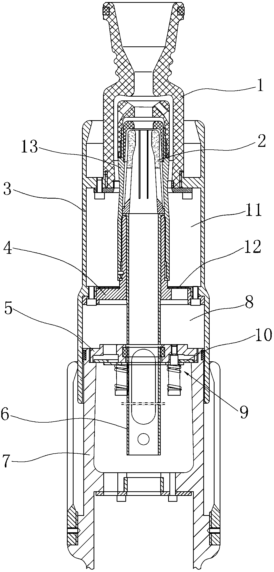
[0012] The present invention is described in detail below in conjunction with accompanying drawing:

[0013] combine figure 1 , The elastic pressure relief system for reducing the operating work of the circuit breaker includes a spout 1, a moving arc contact 2, a cylinder 3, a first flange 4, a second flange 5, a tie rod 6, and a cylinder seat 7. The lower part of the spout 1 is fixed on the upper part of the inner side of the cylinder 3, the upper part of the spout 1 protrudes from the inner side of the cylinder 3, the upper end of the moving arc contact 2 extends into the spout 1, and there is a gap between the moving arc contact 2 and the spout 1, The lower end of the moving arc contact 2 is connected with the inner wall of the cylinder 3 by the first flange 4 . The lower part of the cylinder 3 is set on the cylinder block 7, the upper end cover of the cylinder block 7 has a second flange 5, the tie rod 6 passes through the second flange 5 and is fixedly connected with the...


PUM


Abstract

The invention discloses an elastic pressure relief system for reducing breaker operation work. The elastic pressure relief system comprises a nozzle, a movable arc contact, a cylinder, a first flange, a second flange, a pull rod and a cylinder seat. The lower portion of the nozzle is fixed on the upper portion of the inner side of the cylinder, the upper portion of the nozzle extends out of the inner side of the cylinder, the upper end of the movable arc contact extends into the nozzle, an interval is reserved between the movable arc contact and the nozzle, and the lower end of the movable arc contact is connected with an inner side wall of the cylinder through the first flange. The lower portion of the cylinder is sleeved on the cylinder seat, an upper end cover of the cylinder seat is provided with the second flange, and the pull rod penetrates through the second flange to be fixedly connected with the first flange and drives the first flange to drive the cylinder to move. The first flange, the cylinder and the second flange are enclosed to form an air pressing chamber, and a pressure reducing valve and an air returning valve are arranged on the second flange. The pressure relief system is simple in structure, can effectively reduce the breaker operation work and does not influence arc quenching effect.

Description

technical field [0001] The invention relates to a circuit breaker part of a switchgear, in particular to a pressure relief structure for a moving contact part of a circuit breaker. Background technique [0002] The compressed air arc extinguishing of the circuit breaker is to extinguish the arc by compressing the gas in the compressed air chamber to generate air flow. The existing circuit breaker arc extinguishing chamber includes a static contact module, a moving contact module, a compressed air cylinder and a piston. The piston and A compressed air chamber is formed between the compressed air cylinders. The movable contact module is connected with the air cylinder, and the air cylinder drives the movable contact module to move relative to the piston, so as to change the volume of the air chamber. During the opening operation, the gas in the compression chamber is compressed, and the arc combustion causes the gas to expand, so that the gas pressure in the compression chamb...

Claims


Application Information

Patent Timeline
IPC IPC(8): H01H33/867
Inventor 孔祥冲杨坤彭凤娟张世晓杨发强张成浩王淑芳
Owner YIHE ELECTRIC GRP
Why Eureka
Try Eureka