Compressed-air type arc extinguishing chamber capable of moving bidirectionally

A bi-directional motion and arc extinguishing chamber technology, which is applied in the direction of high-voltage air circuit breakers, electrical components, high-voltage/high-current switches, etc., can solve the problems of redundant mechanical design strength, increased vibration, and many parts

CN112713054AInactive Publication Date: 2021-04-27PINGGAO GRP +1
0 Cites 2 Cited by

Patent Information

Authority / Receiving Office
CN · China
Patent Type
Applications(China)
Current Assignee / Owner
Publication Date
2021-04-27
Estimated Expiration
Not applicable · inactive patent

Smart Images

  • Figure 1
    Figure 1
  • Figure 2
    Figure 2
  • Figure 3
    Figure 3
Patent Text Reader

Abstract

The invention relates to a compressed air type arc extinguishing chamber capable of moving in two directions. The compressed air type arc extinguishing chamber comprises a double-acting hydraulic cylinder, and the double-acting hydraulic cylinder comprises a cylinder body; the cylinder body is fixed at a static end assembly, an inner cavity and an outer cavity are formed in the cylinder body, a static piston rod is arranged in the inner cavity, the movable piston rod and the static piston rod respectively comprise a plug body and a rod body, and the rod bodies of the static piston rods comprise a first rod body and a second rod body; the outer chamber is an annular chamber and surrounds the outer side of the inner chamber, and a movable piston rod is arranged in the outer chamber; the movable end assembly is in transmission connection with the movable side rod body so as to drive the movable side rod body and the movable side plug body to move forwards and backwards during opening and closing; the static arc contact is fixed on the static piston rod; cavity communicating channels are formed in the two axial ends of the double-acting hydraulic cylinder correspondingly and used for communicating the corresponding ends of the inner cavity with the corresponding ends of the outer cavity, so the static piston rod and the movable side rod body are in linkage, and the movable end assembly is buffered. The double-acting structure can meet the double-acting requirement of the compressed air type arc extinguishing chamber under the working conditions of high voltage class and strong impact.
Need to check novelty before this filing date? Find Prior Art

Description

technical field

[0001] The invention relates to a bidirectionally movable compressed gas type arc extinguishing chamber. Background technique

[0002] The interrupter is the core component of the high-voltage switch circuit breaker, which has a decisive impact on the breaking performance, reliability, operating power and economy of the circuit breaker. At present, the structures of arc extinguishing chambers at home and abroad generally use two types: single-acting and double-acting. The single-acting type means that the moving end of the arc-extinguishing chamber moves under the driving mechanism to complete the opening and closing process; the double-acting type interrupting chamber not only moves the moving end, but also Moreover, some components at the fixed end of the arc extinguishing chamber can also be moved. The advantage of the double-moving interrupter is that through the relative movement of the moving and static ends, the moving speed of the moving interrupter ...

Examples

Embodiment 1

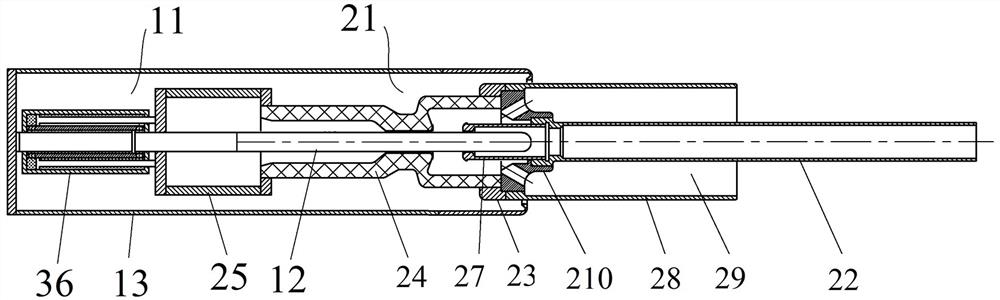
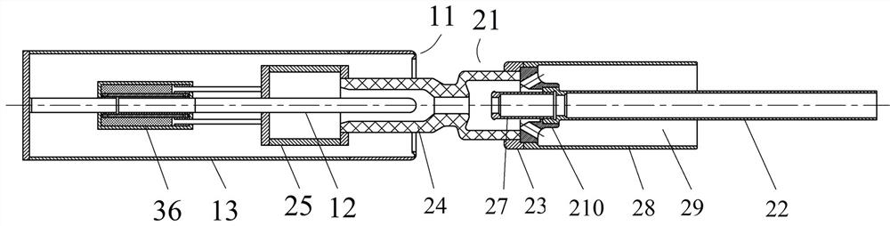
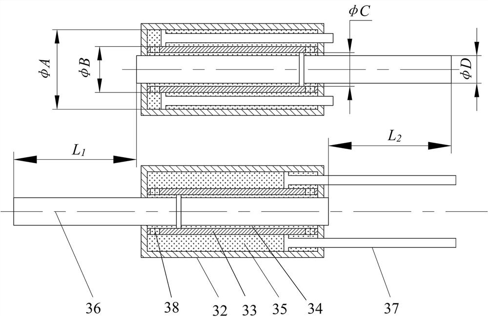
[0045] Such as figure 1 , figure 2 with image 3 As shown, the bidirectionally movable compressed air interrupter includes a static end assembly 11 , a moving end assembly 21 and a double-acting hydraulic cylinder 31 . The static end assembly 11 includes a static arc contact 12, which is guided along the front and rear directions; the moving end assembly 21 includes an insulating pull rod 22, a moving main contact 23, a large nozzle 24, a moving arc contact 27 and a connecting cylinder 25 , also includes the compression cylinder structure, the compression cylinder structure is the same as the prior art, including the compression cylinder 28, the compression cylinder 28 is used to form the compression chamber 29, the compression cylinder 28 is provided with a tie rod connection seat 210, and the tie rod connection seat 210 is used for insulating The pull rod 22 is fixedly connected, and a gas channel is arranged on it for the gas in the compressed gas chamber 29 to be discha...

Embodiment 2

[0058] The difference between this embodiment and Embodiment 1 is that in Embodiment 1, radial through holes are provided on the isolation cylinder 33, and the chamber communicating channel 38 is formed by radial through holes, while in this embodiment Among them, the end surfaces of the inner chamber 34 and the outer chamber 35 are provided with communication holes, and the inner chamber 34 and the outer chamber 35 are communicated through a pipeline connected between the two communication holes.

Embodiment 3

[0060] The difference between this embodiment and Embodiment 1 is that in Embodiment 1, the isolation cylinder 33 directly separates the inner chamber 34 and the outer chamber 35, while in this embodiment, the inner chamber 34 and the outer chamber An annular cavity is provided between the chambers 35 .